


Hardware Wiring, Network Setup & Project Initialization
Tutorial
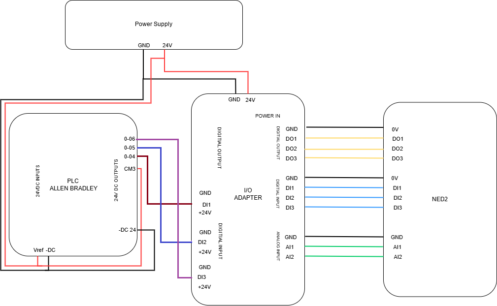
Electrical diagram using I/O Adapter (For Modbus implementation skip this diagram):
In this first phase of the tutorial, we will see how to connect the I/O Adapter to both the Allen-Bradley PLC and the Ned2 robot. For this, a 24V power supply is required to power the I/O Adapter. To power the PLC output channels, bridge the PLC’s +24V terminal to the common output supply terminal (often labeled as L+ to 1L or +V/+24V depending on your PLC model). Here are the connections to follow:
Interface configuration in Connected Components WorkBench
Download Connected Components WorkBench (CCW)
Use this link to access the latest version of Connected Components Workbench (CCW).
To download the software, you must create a Rockwell Automation account and fully complete your profile (including your company name and residing location).
Important: Location verification requests can take 24 to 48 hours to be approved before file downloads are granted. Complete this step ahead of time.

When prompted on the Rockwell download page, select only the following components to minimize file size and installation time:
-
Connected Components Workbench Standard Edition (Main software)
-
CCW Patch (Recommended for system stability)
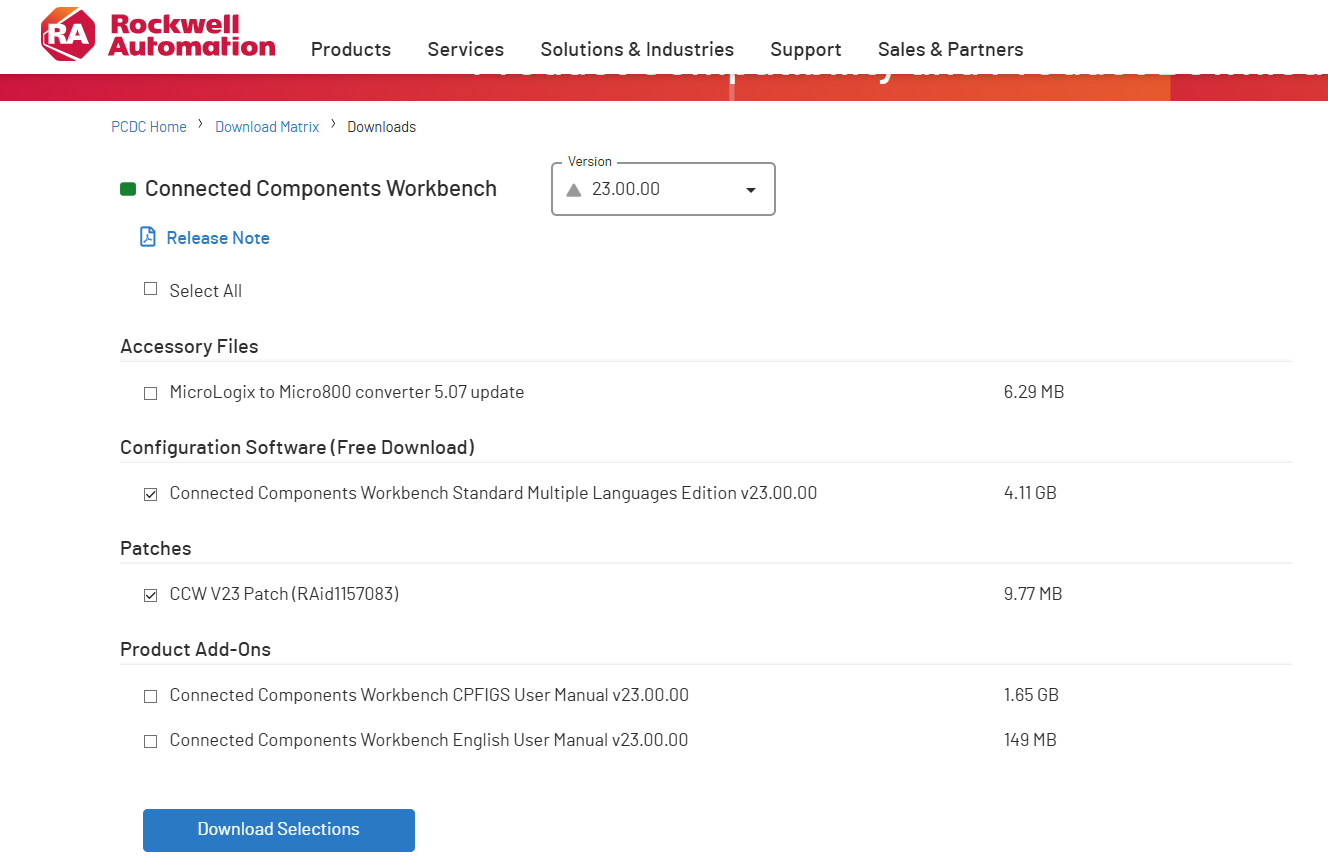
You can follow this video tutorial if you get stuck, and make sure to select the latest available version. After downloading and installing the software, we will complete a few initial setup steps before we start programming the PLC.
Network Configuration Setup
Before connecting to the PLC and the Ned2 robot, you must configure your computer’s network adapter with a static IP address on the same subnet (e.g., 192.168.1.100 with Subnet Mask 255.255.255.0). This ensures direct communication with both devices without IP conflicts.
Leave the Gateway and DNS fields empty, as a local industrial setup does not require internet routing.
Step-by-Step OS Setup
Windows (10 / 11)
-
Open the Start Menu (
Win) or pressWin + R, typencpa.cpl, and press Enter to open Network Connections. -
Right-click your Ethernet adapter and select Properties.
-
Double-click Internet Protocol Version 4 (TCP/IPv4).
-
Select Use the following IP address.
-
Enter the network parameters:
-
IP address:
192.168.1.100 -
Subnet mask:
255.255.255.0 -
Default gateway / DNS: Leave blank.
-
-
Click OK on both dialog boxes to apply the settings.
Linux (Ubuntu / Debian - GUI)
-
Open Settings and navigate to Network.
-
Click the gear icon ⚙️ next to your active Ethernet interface.
-
Go to the IPv4 tab and select Manual.
-
Enter the network parameters under Addresses:
-
Address:
192.168.1.100 -
Netmask:
255.255.255.0 -
Gateway: Leave blank.
-
-
Click Apply and restart the network connection to toggle changes.
macOS
-
Open System Settings and select Network from the sidebar.
-
Click on your active Ethernet adapter.
-
Click Details... and go to the TCP/IP tab.
-
Set Configure IPv4 to Manually.
-
Enter the network parameters:
-
IP Address:
192.168.1.100 -
Subnet Mask:
255.255.255.0 -
Router: Leave blank.
-
-
Click OK, then click Apply.
Assigning the PLC IP Address
Next, we need to assign an IP address to the PLC. To do this, download the BOOTP-DHCP Commissioning Tool (available here). Connect the PLC to your computer using an Ethernet cable, then open the software. Select your network interface and click OK.
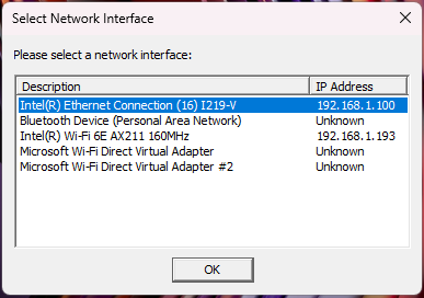
Wait a few seconds for the PLC to appear on the Discovery History list. Once it is displayed, right-click on the device's Ethernet Address (MAC) and select Add Relation.
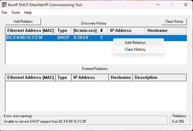
Choose an IP address on the same network as the PC. Then click OK.
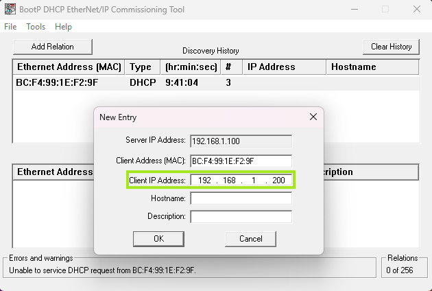
Select the relation in the Entered Relations list and click Disable BOOTP/DHCP. This ensures that the PLC retains the same IP address every time it reboots, instead of having a new one reassigned by the network.
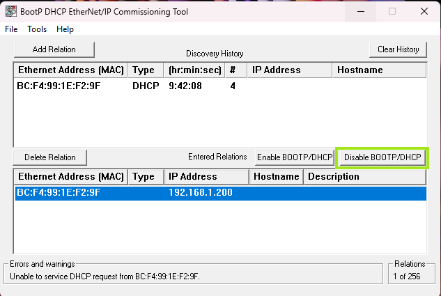
If successful, close the BOOTP-DHCP tool. If an error appears, leave BOOTP enabled for now; we will permanently assign the static IP address inside Connected Components Workbench (CCW).
CCW Setup: Project Creation & PLC IP Configuration
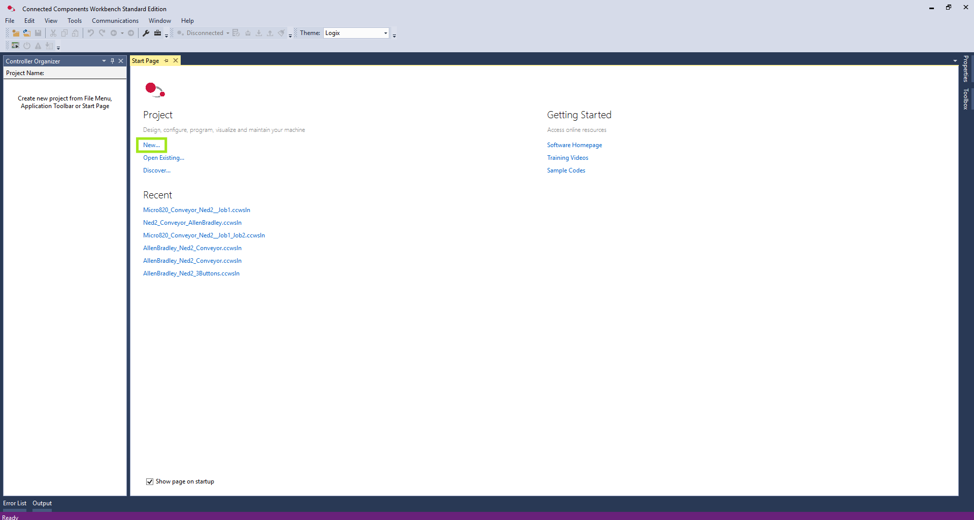
Now, open the CCW software. Create a new project.
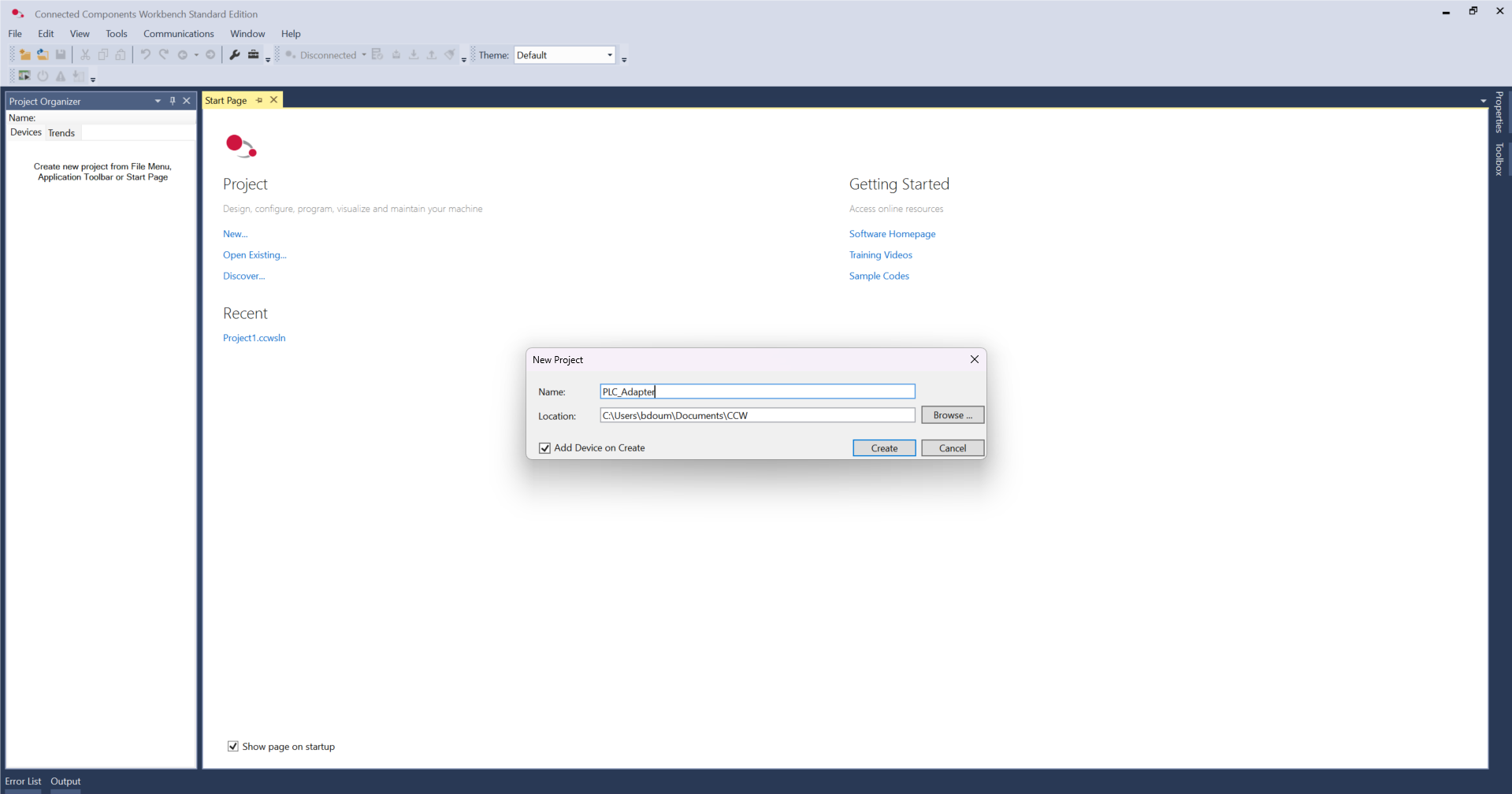
Define a name and click Create.
Wait a few seconds and a pop-up window will appear.
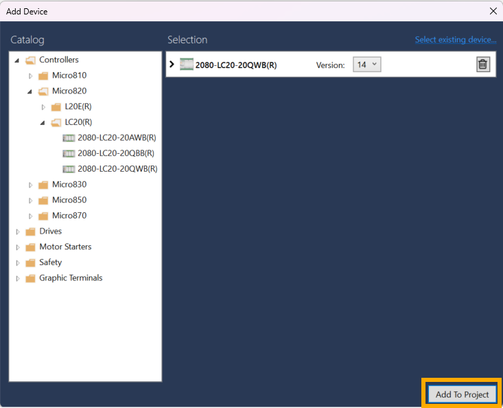
Expand the Controllers folder, select the reference of your PLC.
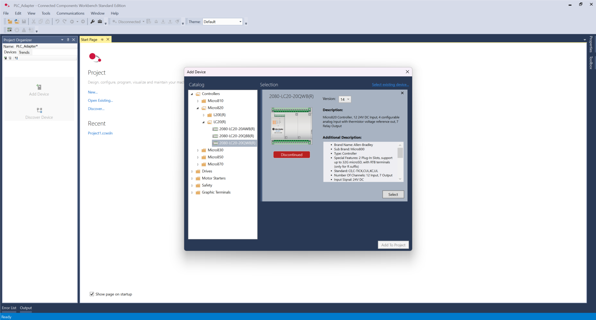
Click Select and Add To Project.
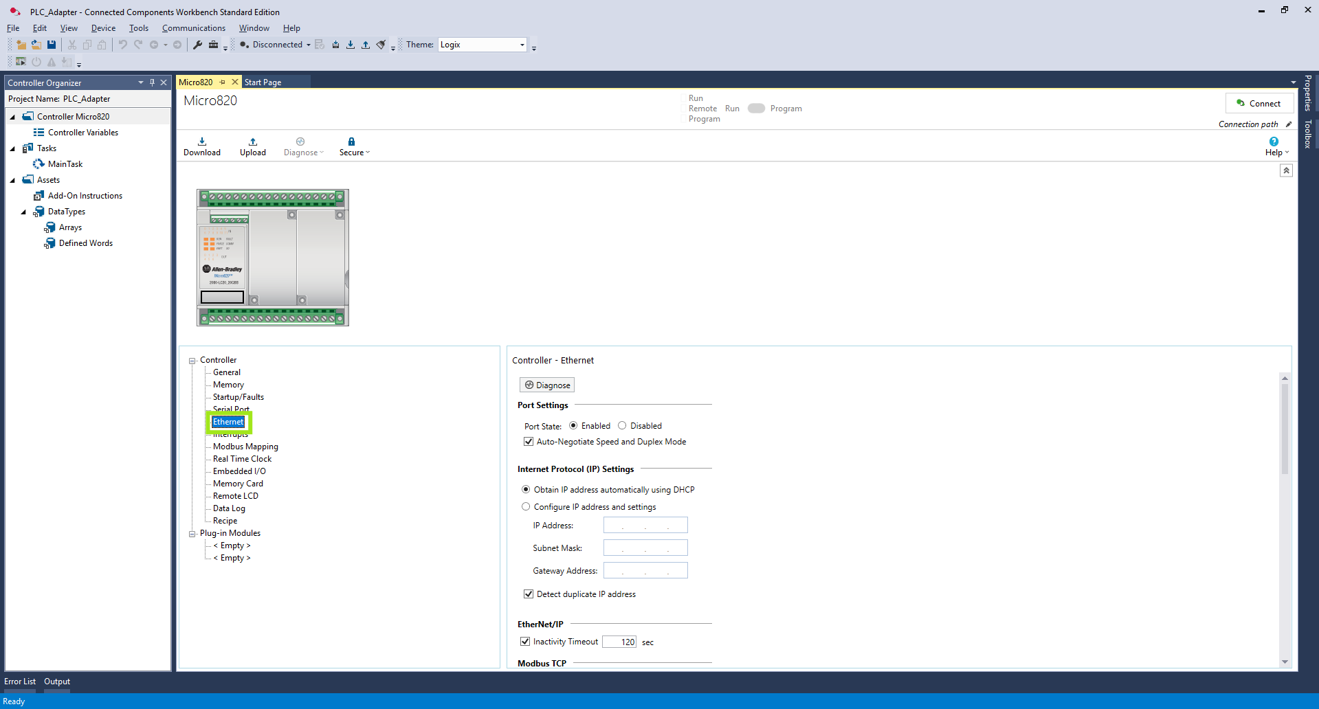
In the main device configuration tab (Micro820) expand the Ethernet section under the controller properties list.
Select Configure IP address and settings. This action automatically disables BOOTP and DHCP on the hardware interface.
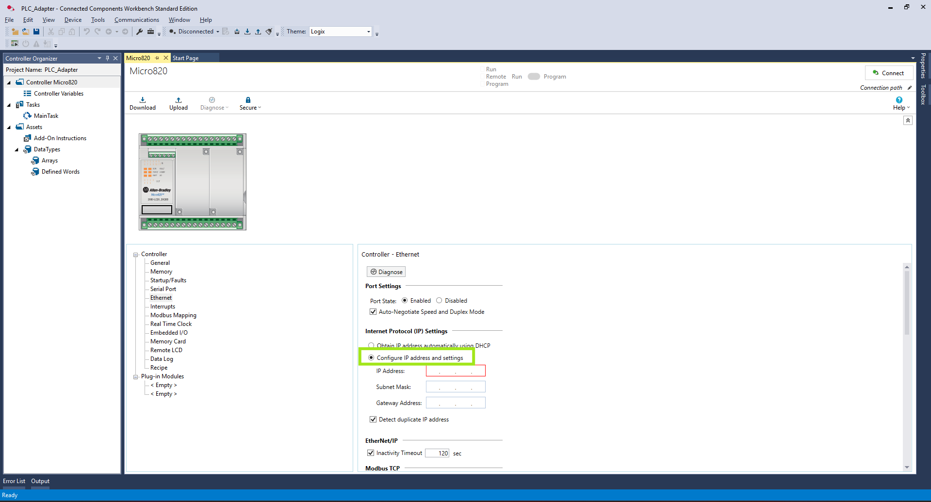
Enter your desired network settings into the fields:
-
IP Address:
192.168.1.200 -
Subnet Mask:
255.255.255.0 -
Gateway / DNS: Leave blank (for local industrial network setups).
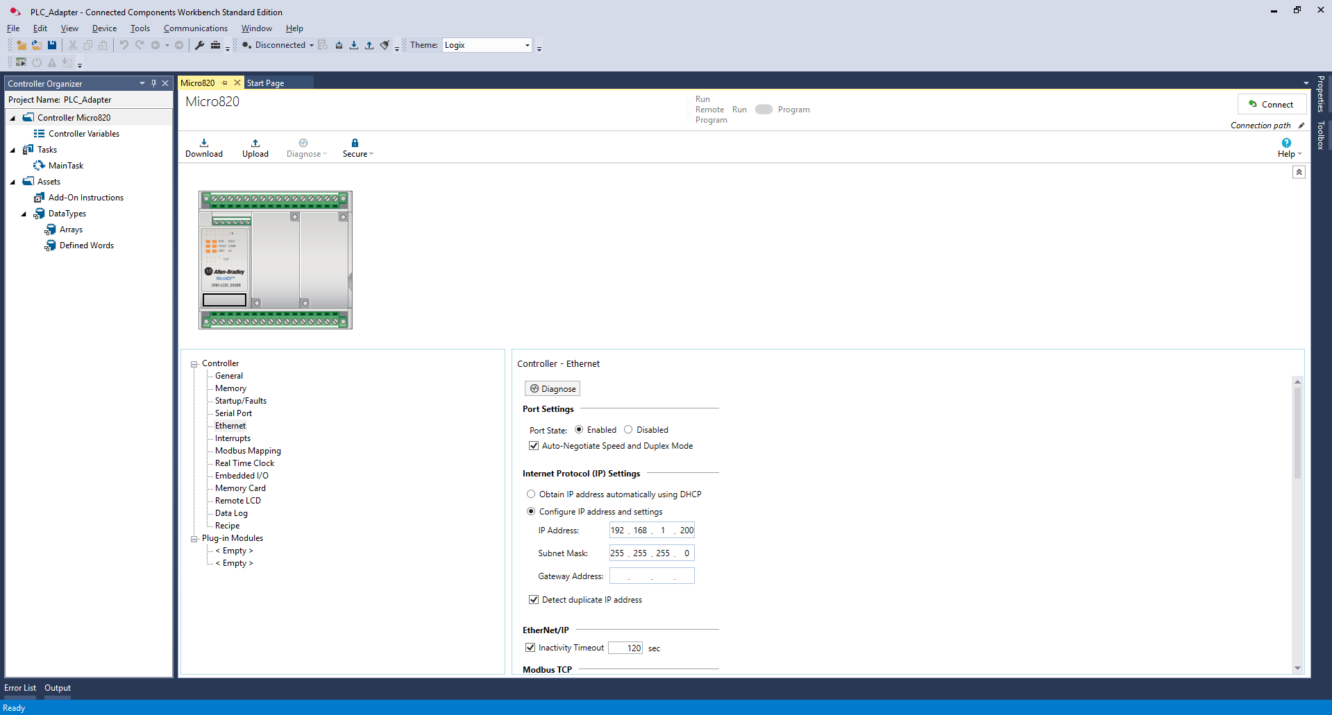
Next, under the View menu, open the Project Organizer.
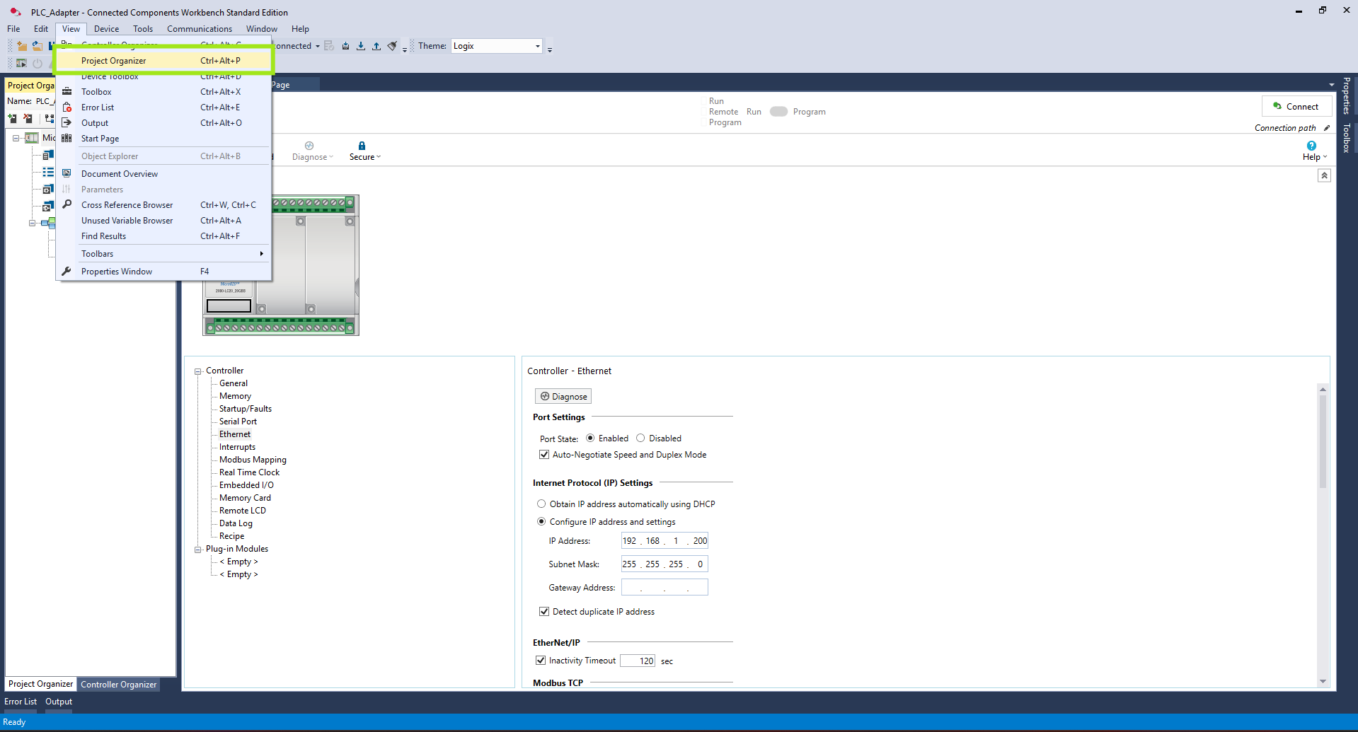
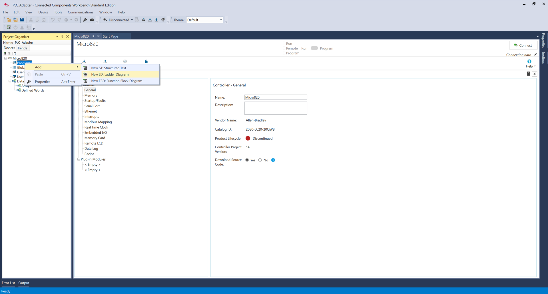
Then, right-click on Programs -> Add -> New LD: Ladder Diagram. Rename the newly created program Main.
Next Steps: Now that your hardware wiring, static networking, and CCW project framework are ready, proceed to the next module to build the ladder logic routines. After completing the base logic setup, you will explore dedicated modules for integrating the Niryo Conveyor Belt and establishing Modbus TCP communication.