Controlling Ned2/Ned3Pro robot via a Siemens PLC and TIA Portal V20 (I/O Adapter)
Tutorial
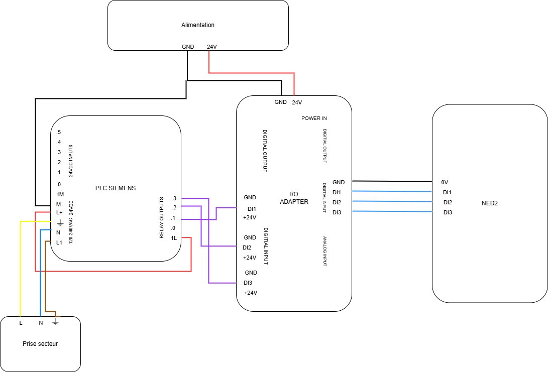
Electrical diagram:
In this first phase of the tutorial, we will see how to connect the I/O Adapter with the Siemens PLC on one side and the Ned2 robot on the other. For this, a power supply that can provide 24 V is necessary (to power the I/O Adapter). We power the PLC outputs with its own 24V (cable connecting L+ to 1L). Here are the connections to follow:
Interface configuration on TIA PORTAL
Subsequently, on the computer, create a new project on TIA PORTAL.
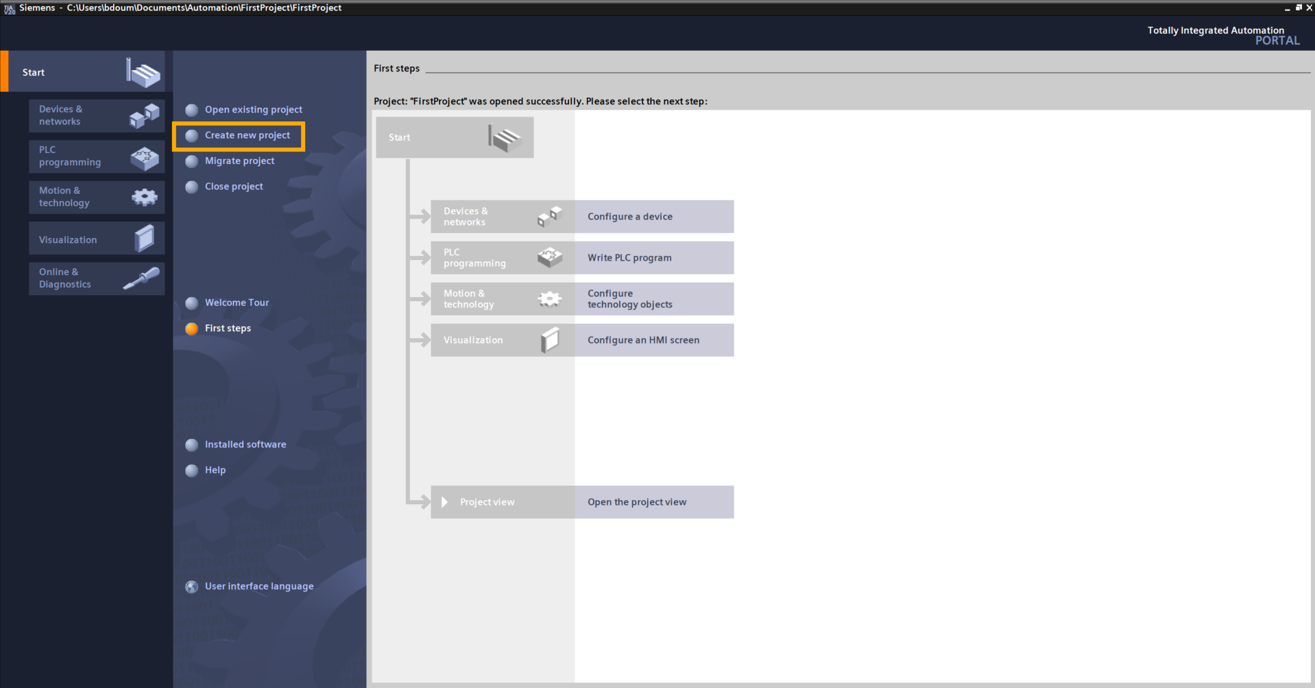
Name it as you wish. In our example, the project is named PLC Adapter:
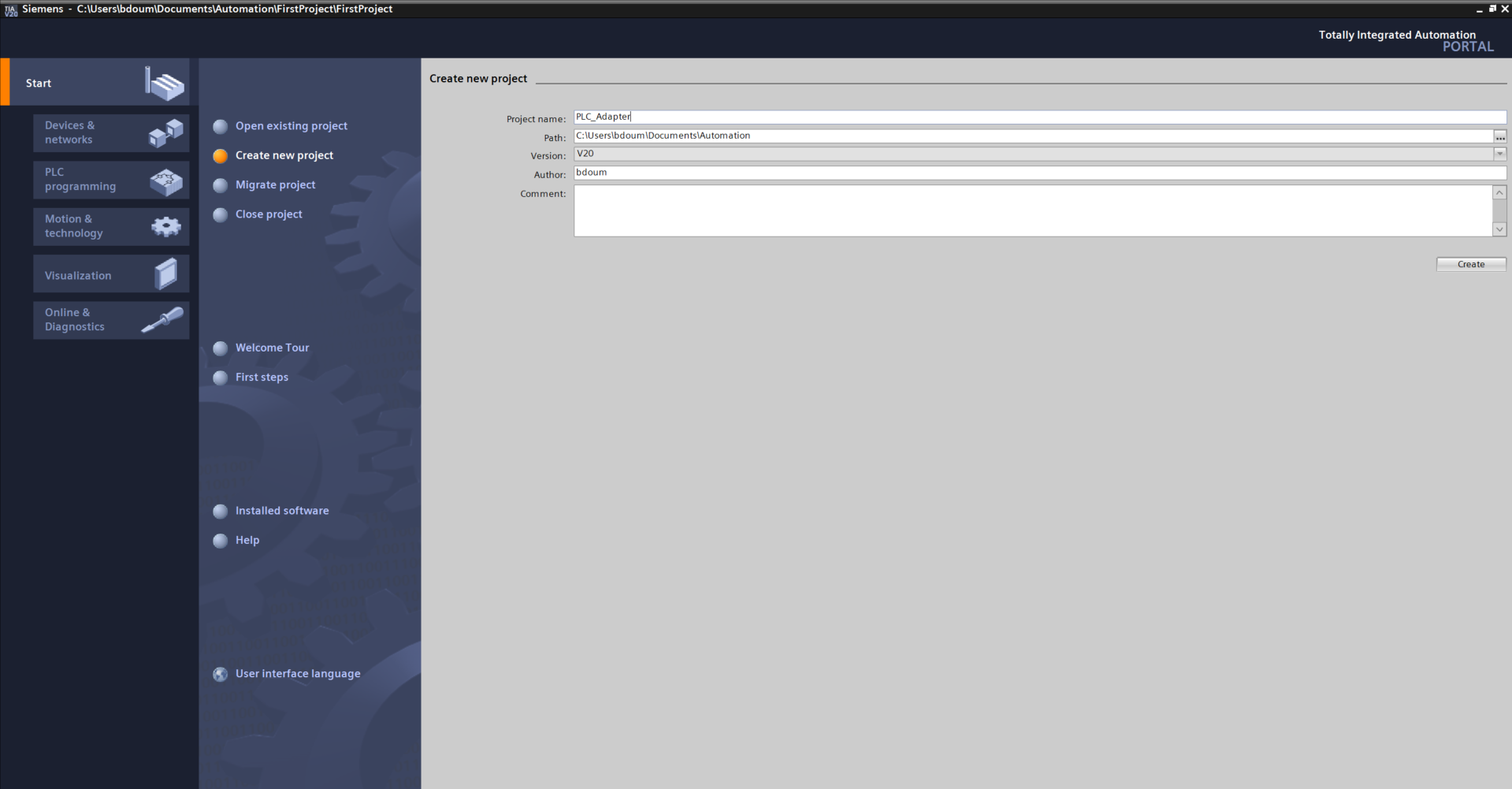
Click on Project view.
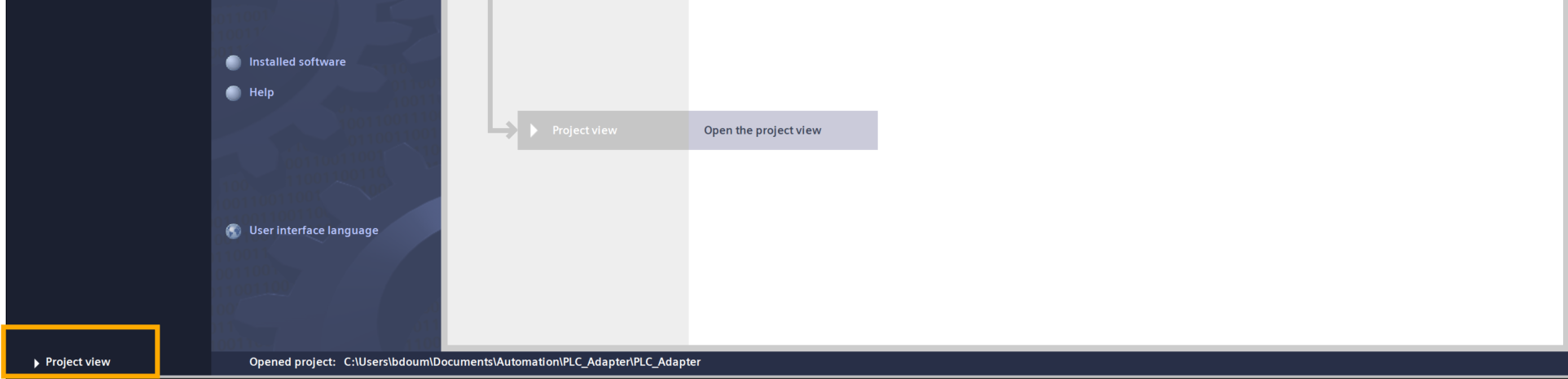
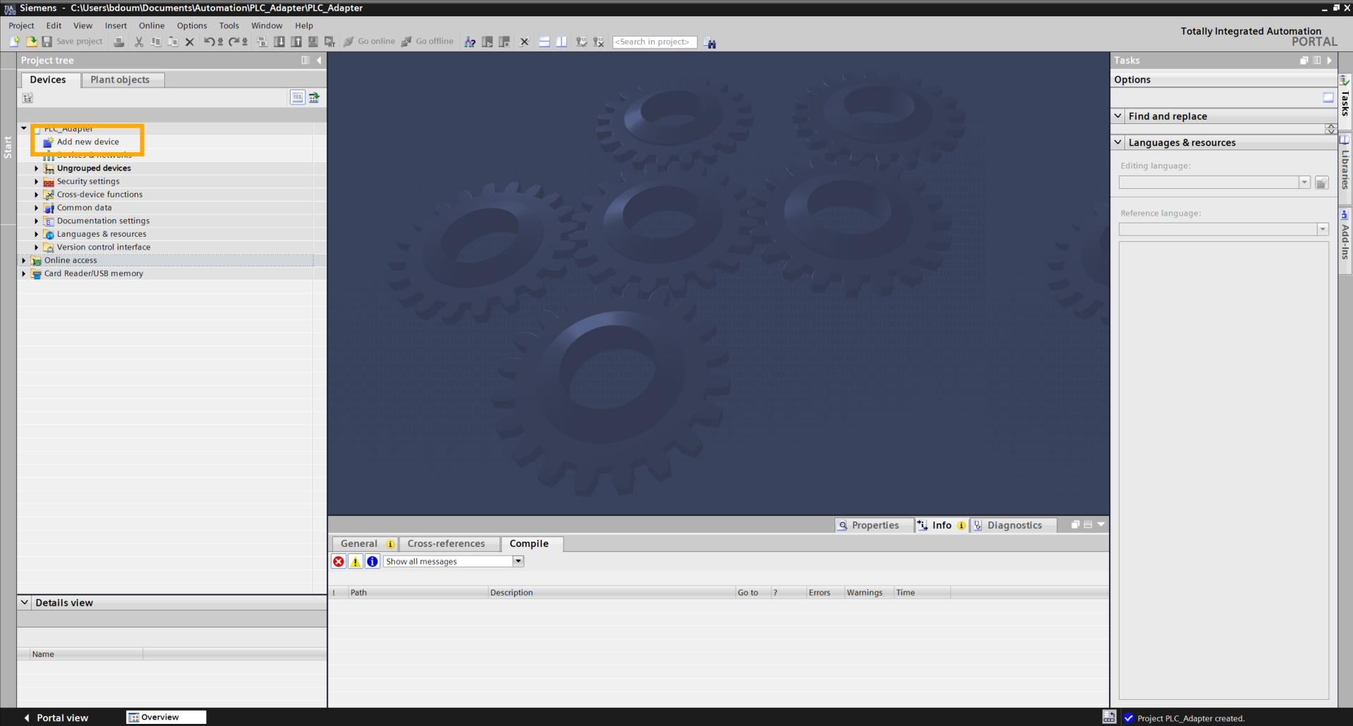
This should lead you to this interface. The next step is to add our PLC with its input and output modules.
To do this, double-click on Add device.
The following window appears.
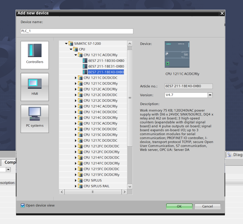
Select the PLC reference in the Controllers window.
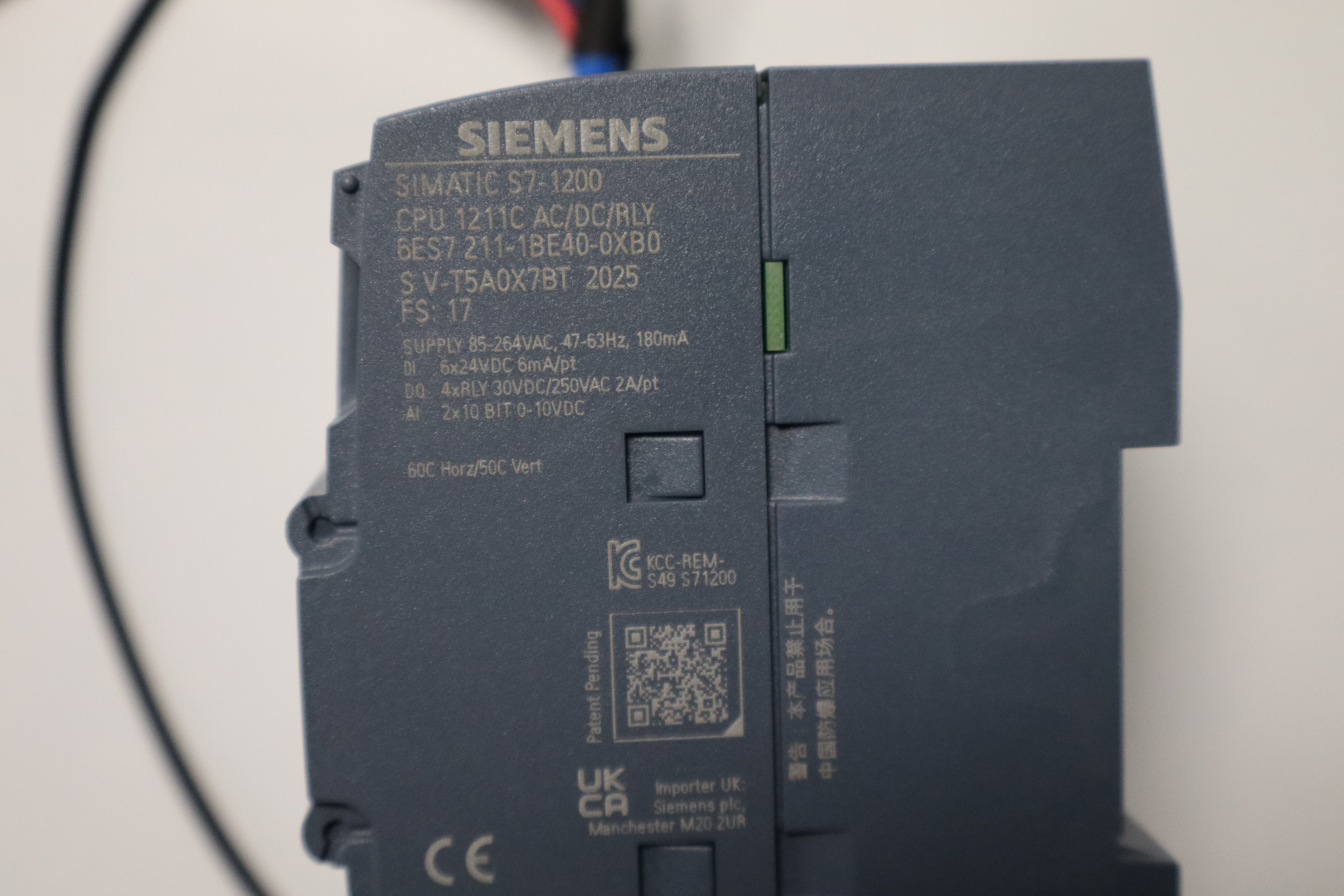
In our case: SIMATIC S7-1200 → CPU 1211 AC/DC/Rly → 6ES7 211-1BE40-0XB0. In case of doubt, the reference can be found on the PLC itself, as shown in the following image.
Click OK.
A window suddenly appears. It allows you to define the security settings when connecting with the PLC.
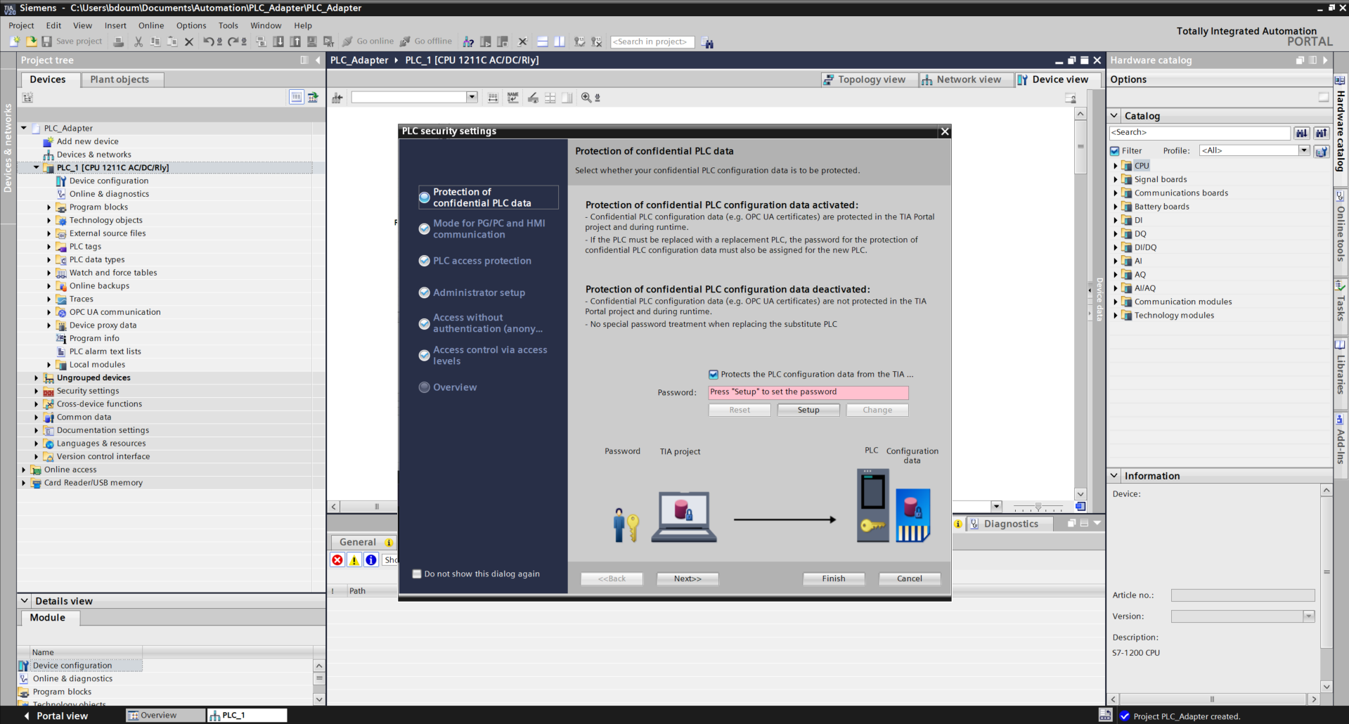
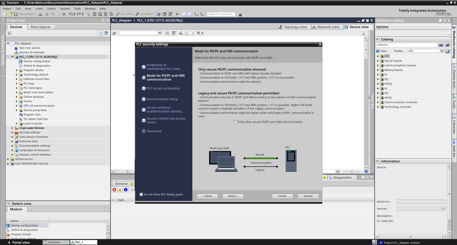
For the purposes of this tutorial, uncheck the box Protects the PLC... Press Next. Do the same on the next page to obtain this type of result.
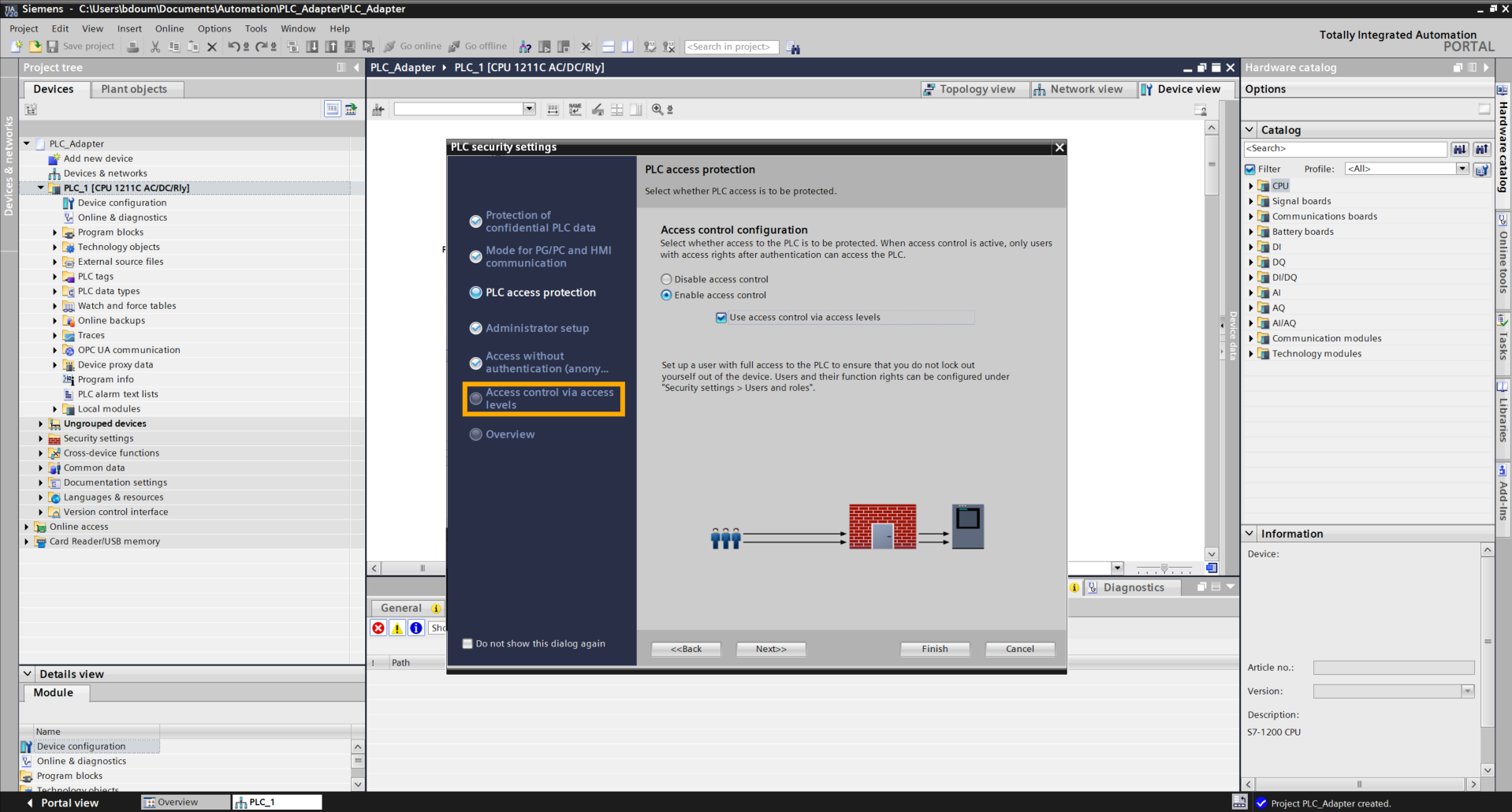
On the next page, select the option Use access control via access levels. Then click directly on the tab Access control via access levels.
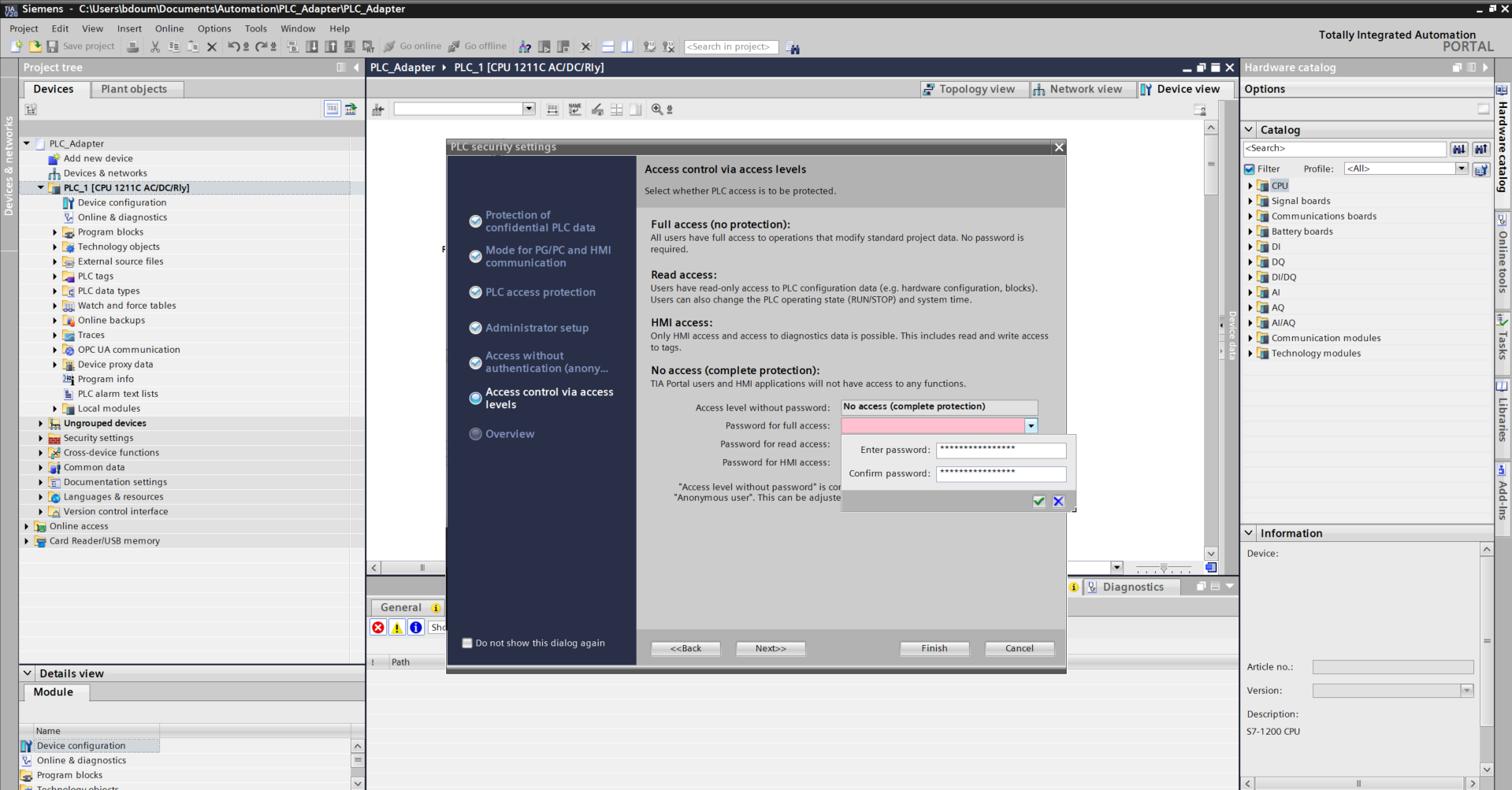
Click on the red field bar at the Full access configuration level and choose a password taking into account the requested requirements.
On the Overview tab, check the following information:
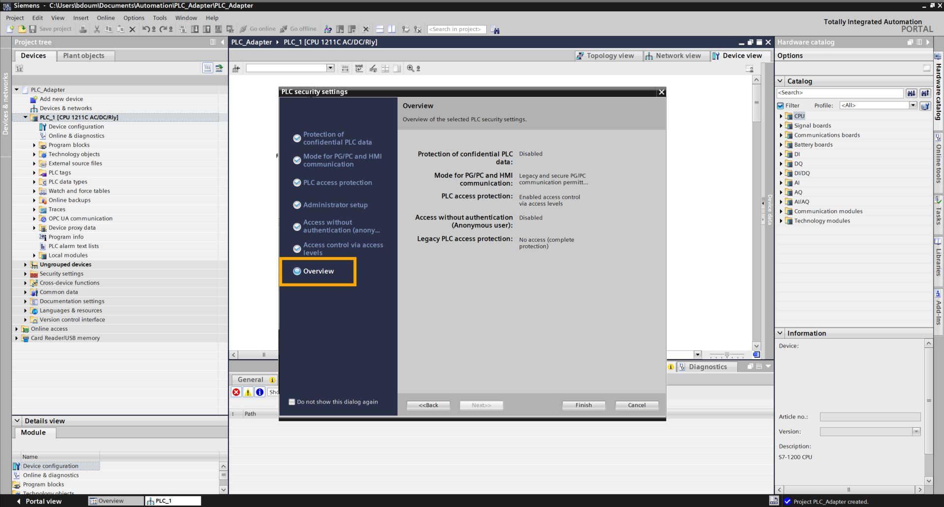
Click on Finish to complete the configuration.
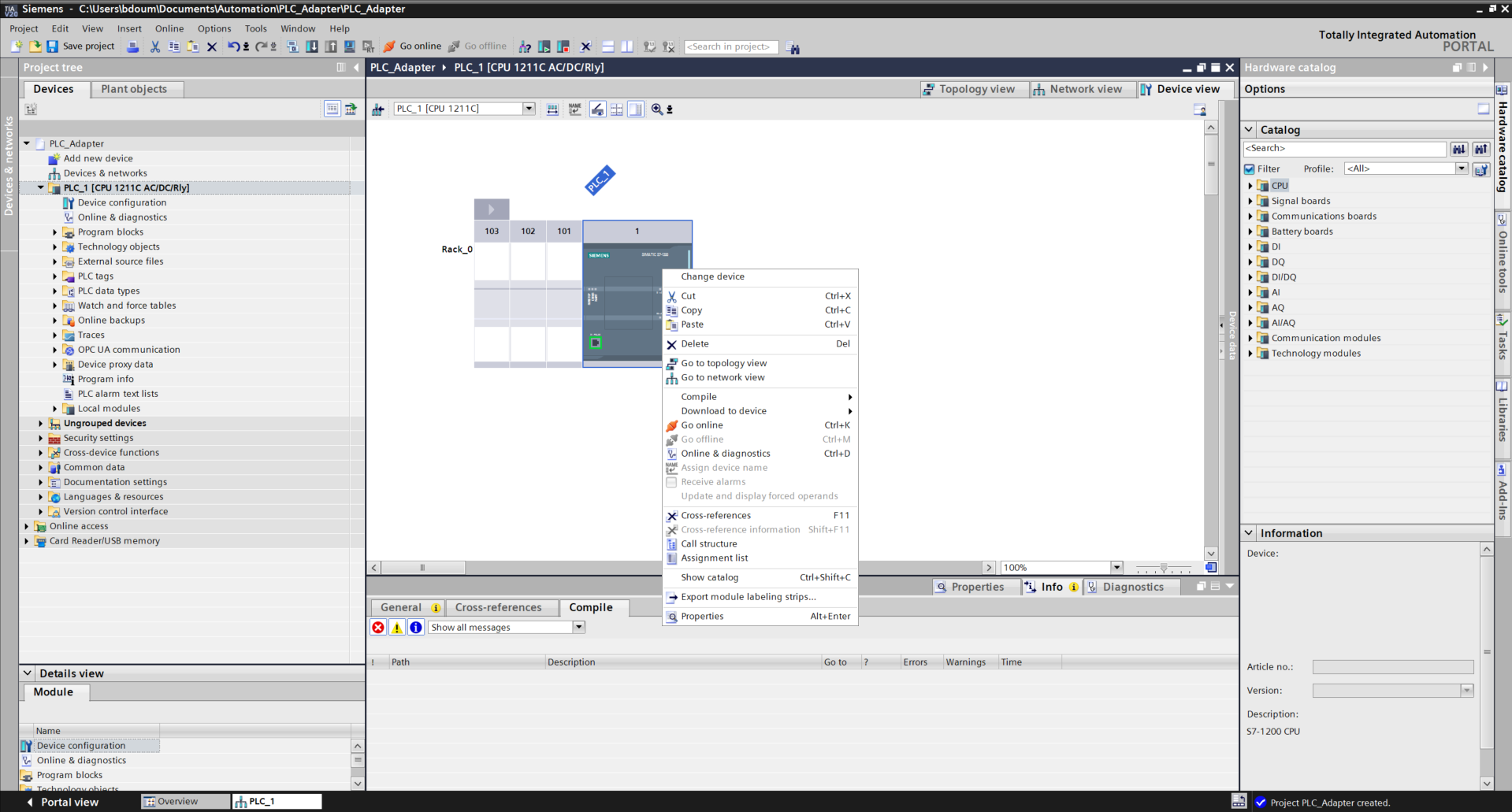
Right-click on the PLC, then go to Properties
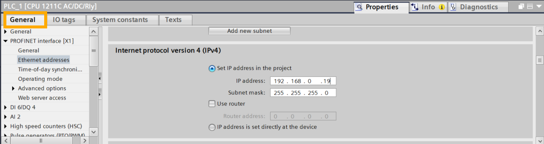
Head to the General tab → PROFINET Interface[X1] → Ethernet addresses → Internet protocol version 4(IPv4).
Enter the available PLC address as shown in the following image. In our example, the IP address is 192.168.0.19.
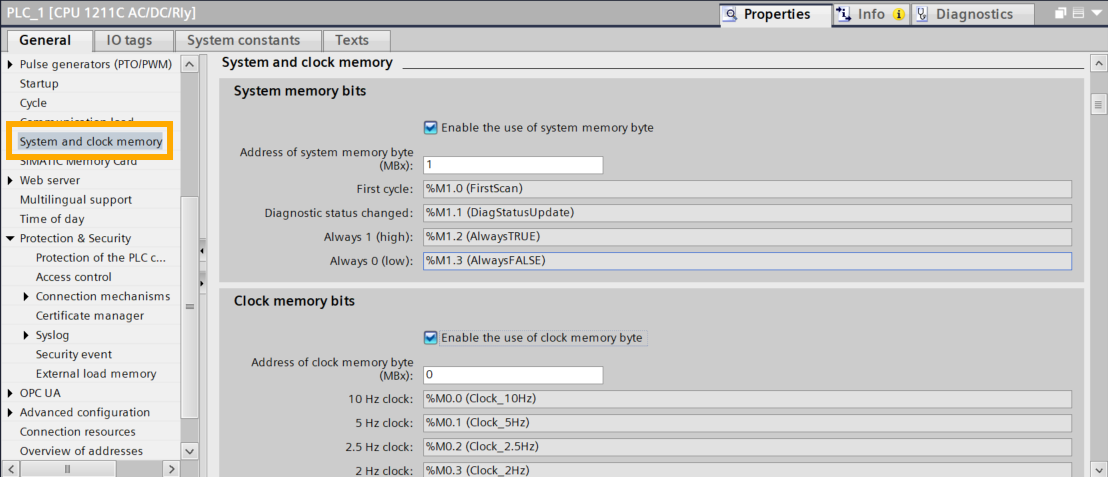
Next, click on System and Clock Memory. Check the two following boxes.
Next, we will proceed with loading the program into the PLC.
Start with the Hardware compilation:
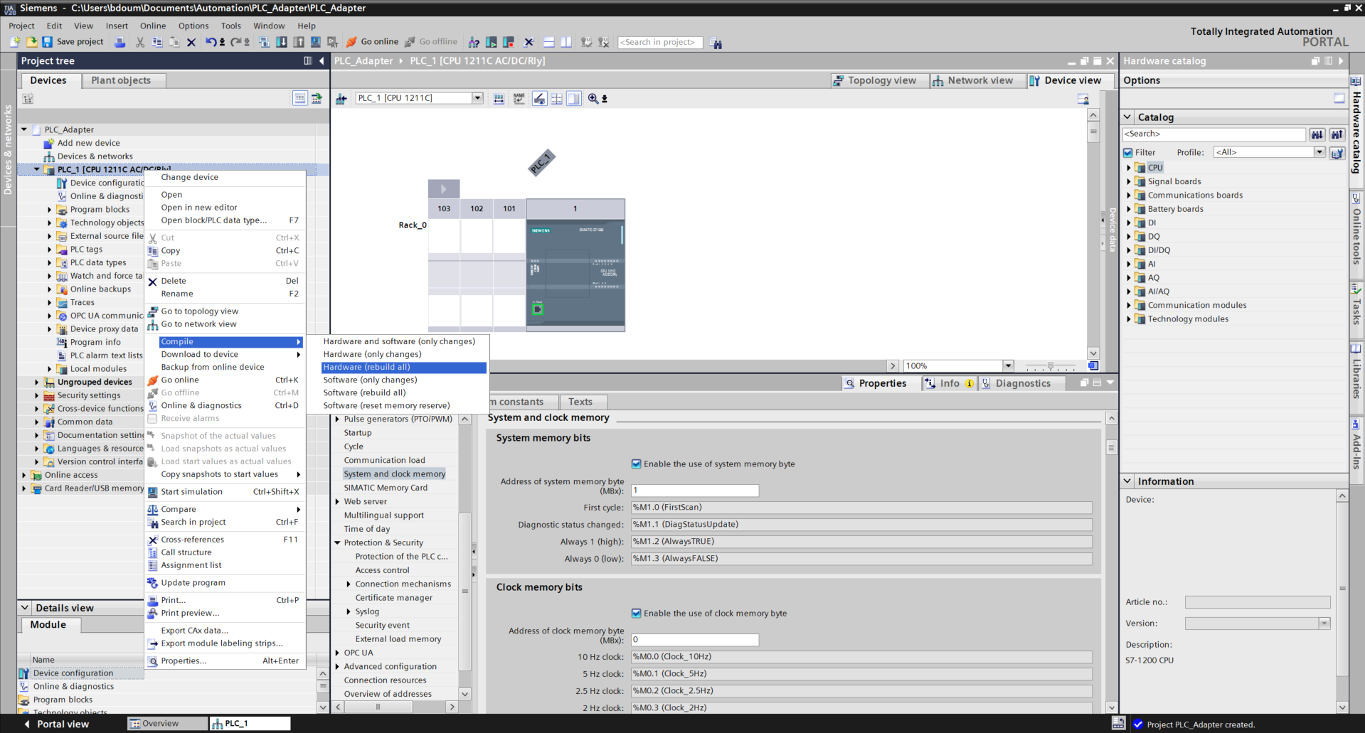
Right-click on the global folder of PLC_1, then go to Compile → Hardware (rebuild All).
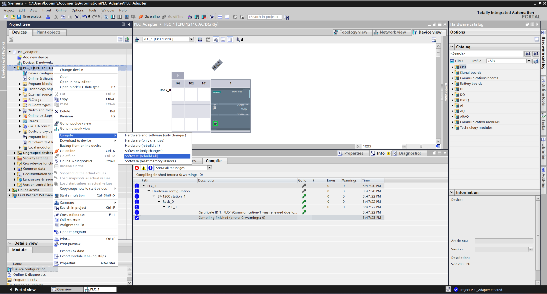
Do the same for the software.
It is time to proceed with loading the program.
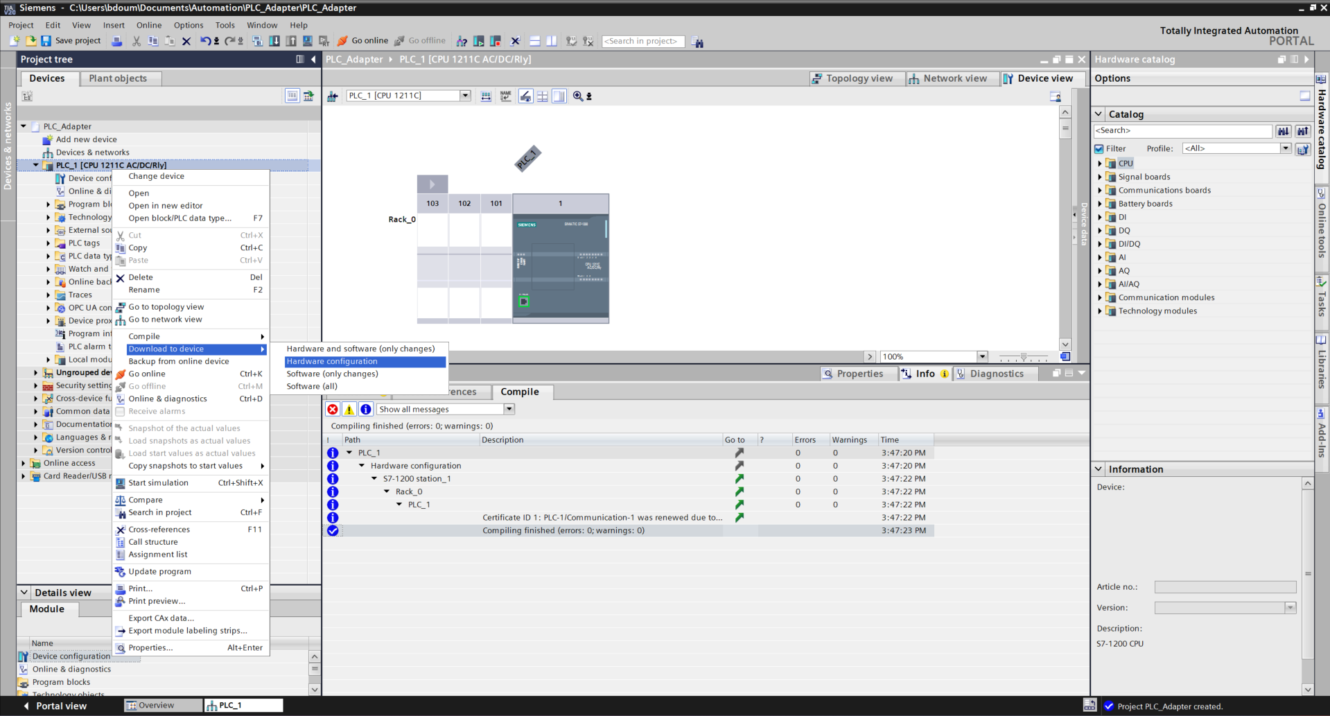
Right-click and go to Download to device→ Hardware configuration.
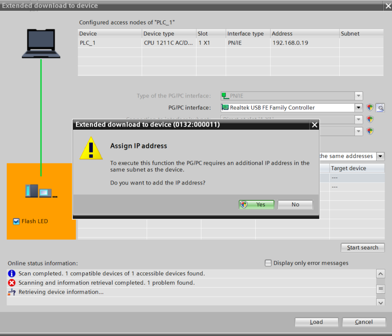
An interface like this one should appear. After a certain time, the PLC is detected. If the search did not start, click on Start Search.
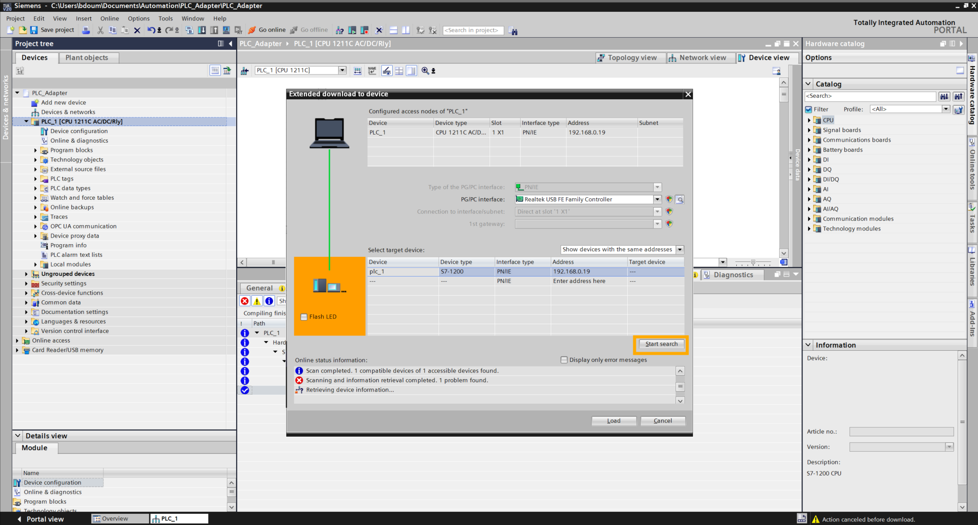
Subsequently, check the Flash LED box to verify that the PLC is correctly connected (pay attention to the LEDs on the PLC). Then click on Load and click on Yes at the message level.
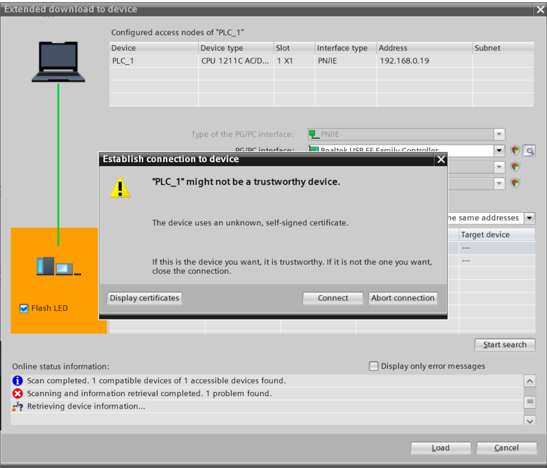
Click on Connect.
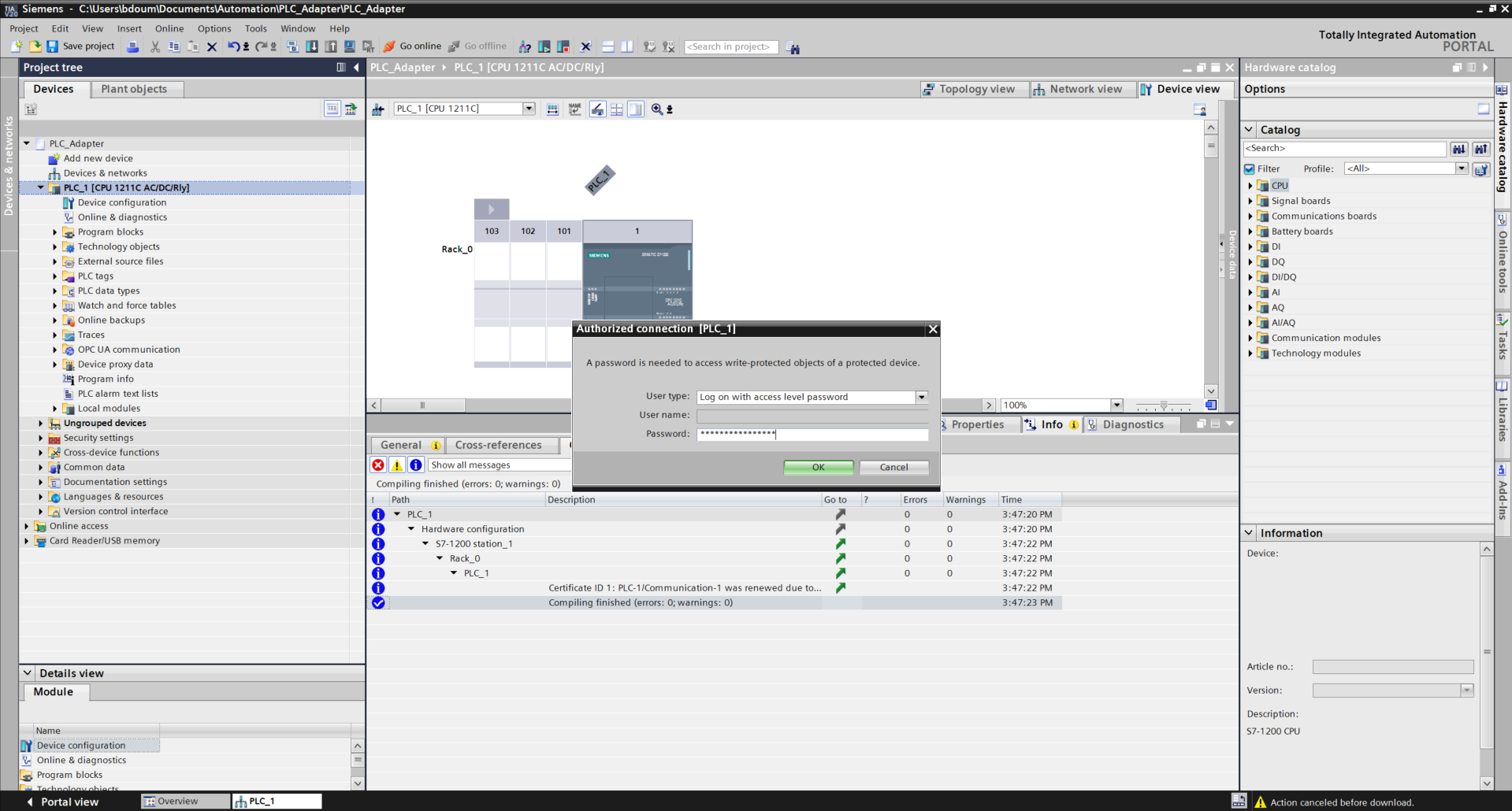
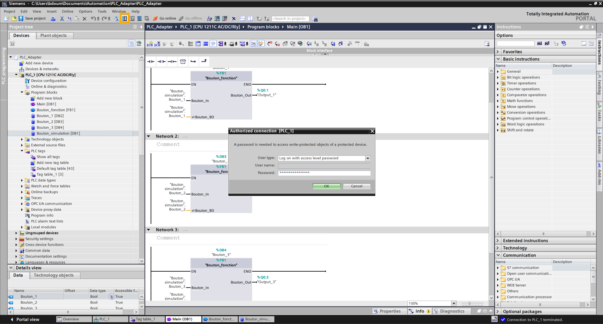
Enter the password defined previously during the security configuration.
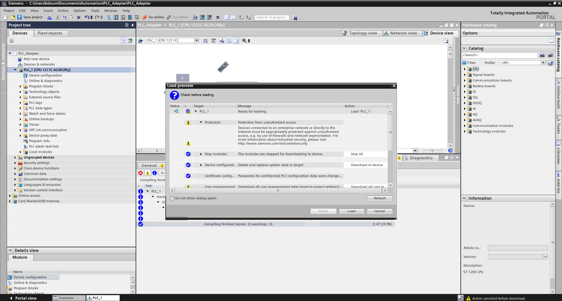
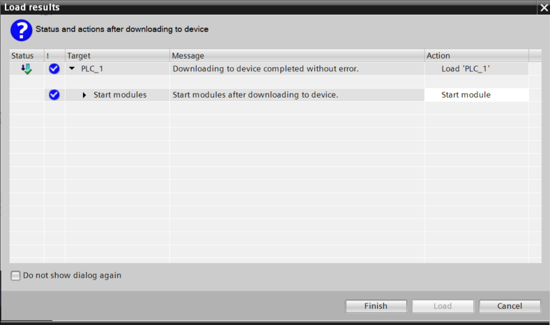
By clicking OK, the following window opens. Click on Load and on Finish.
Click on Go online to verify if the connection is correctly defined.
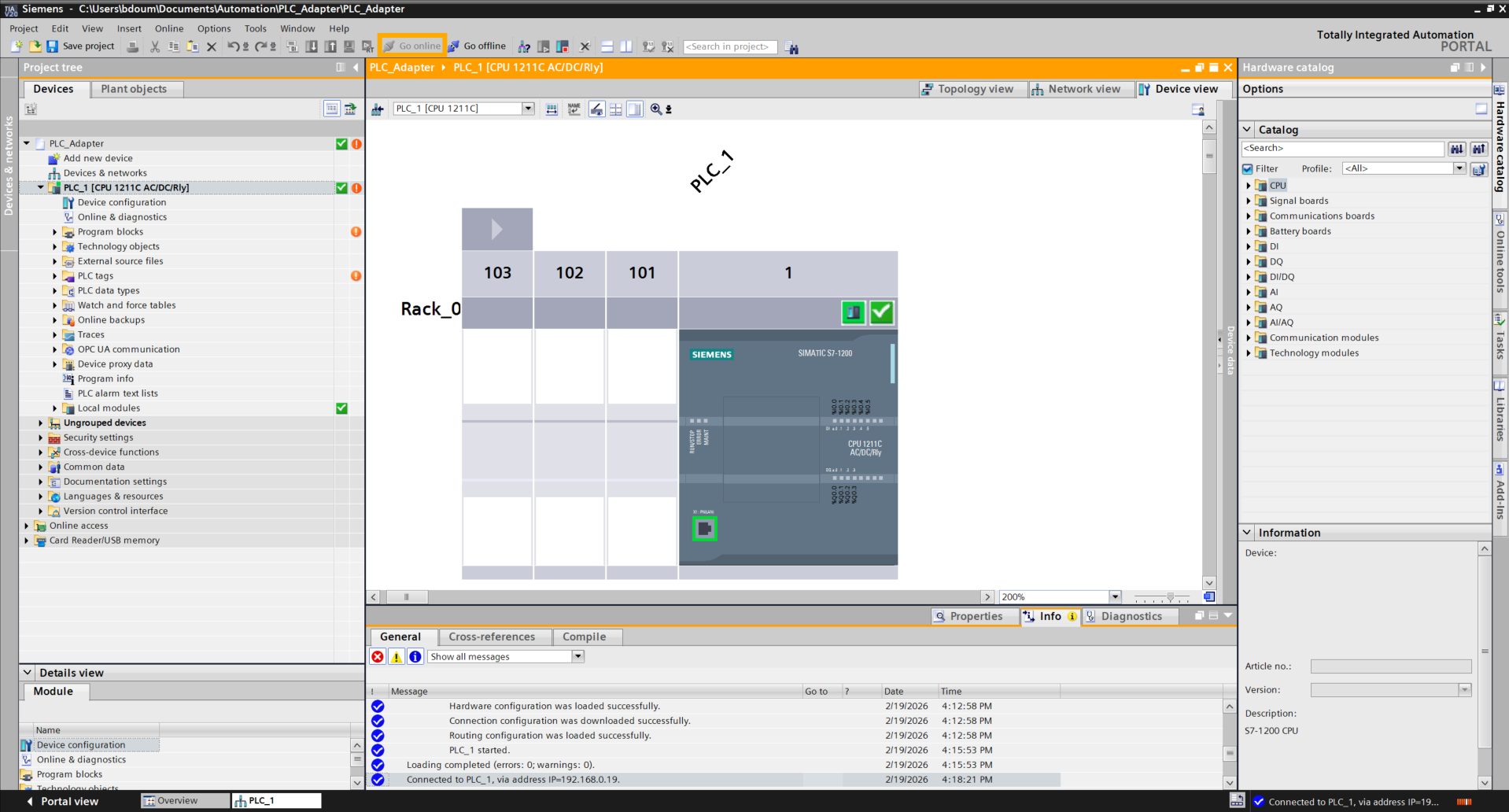
Then click on Go offline.
In this step, we will configure virtual buttons to simulate digital inputs, thus reproducing the behavior of physical push buttons.
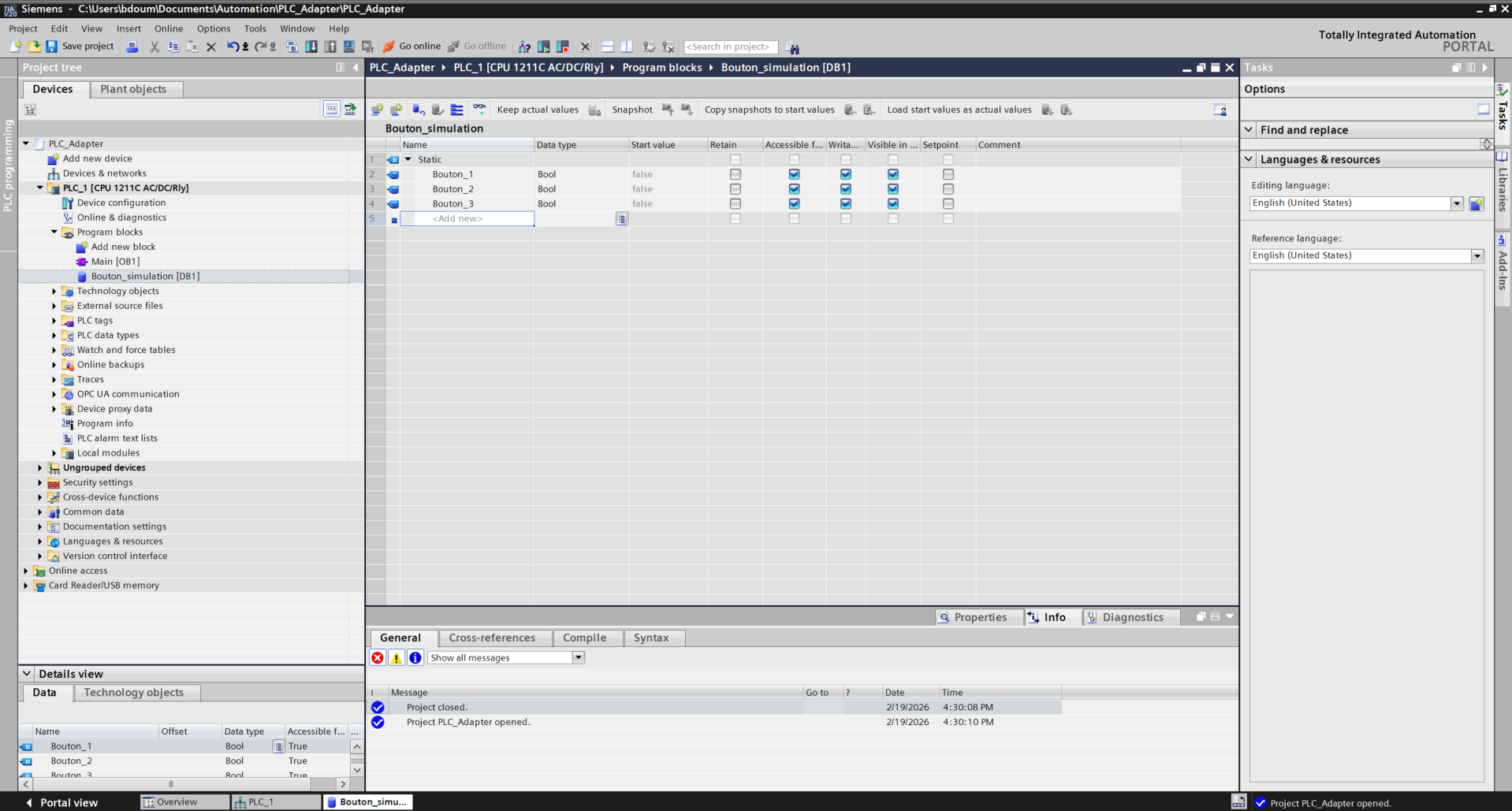
To do this, we will create a database that will contain the variables representing the buttons. Double-click on Add a new block.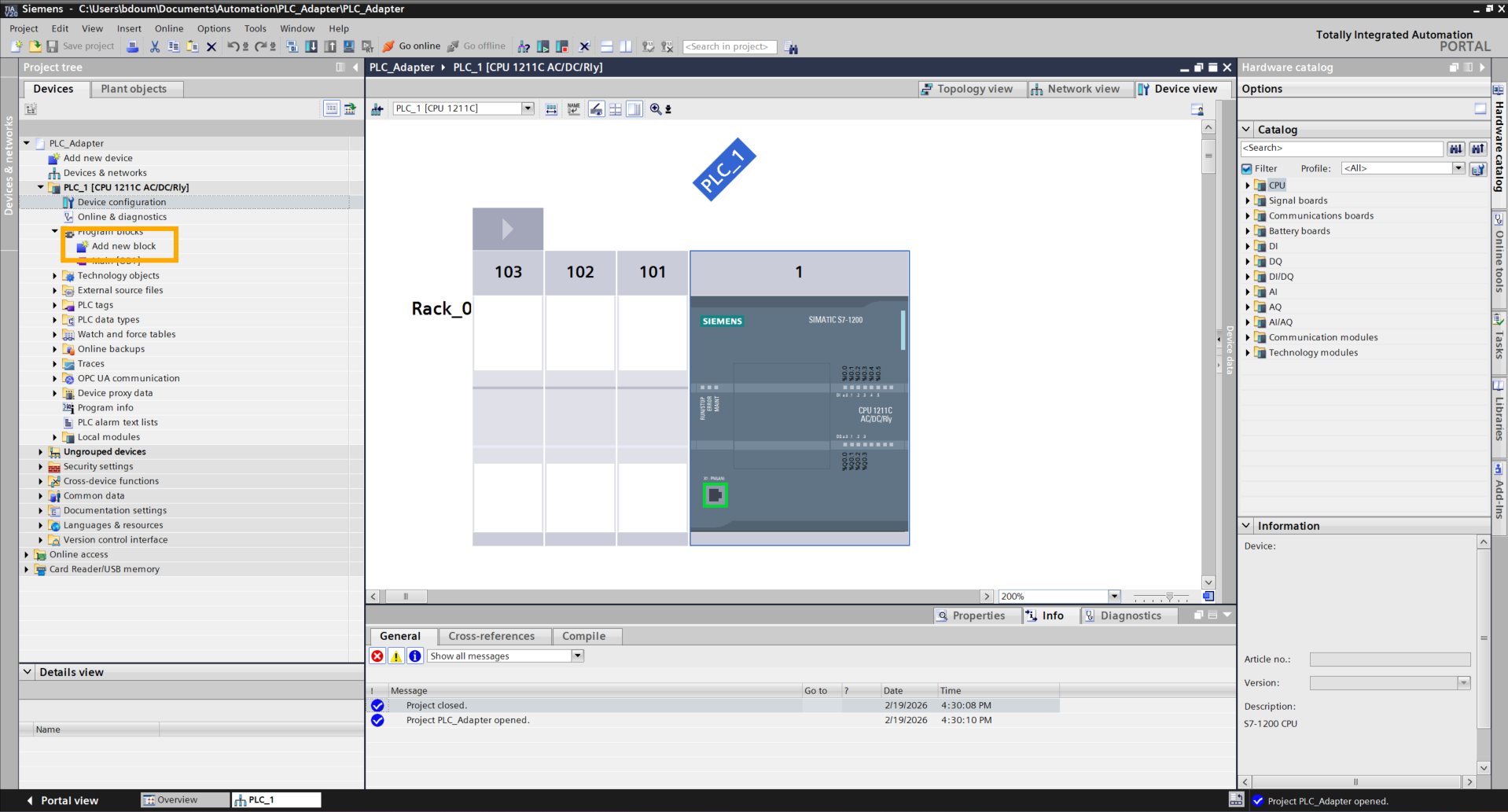
A window like this one appears. Go to the Data block tab and choose a name. For the example, the chosen name is Bouton_simulation. 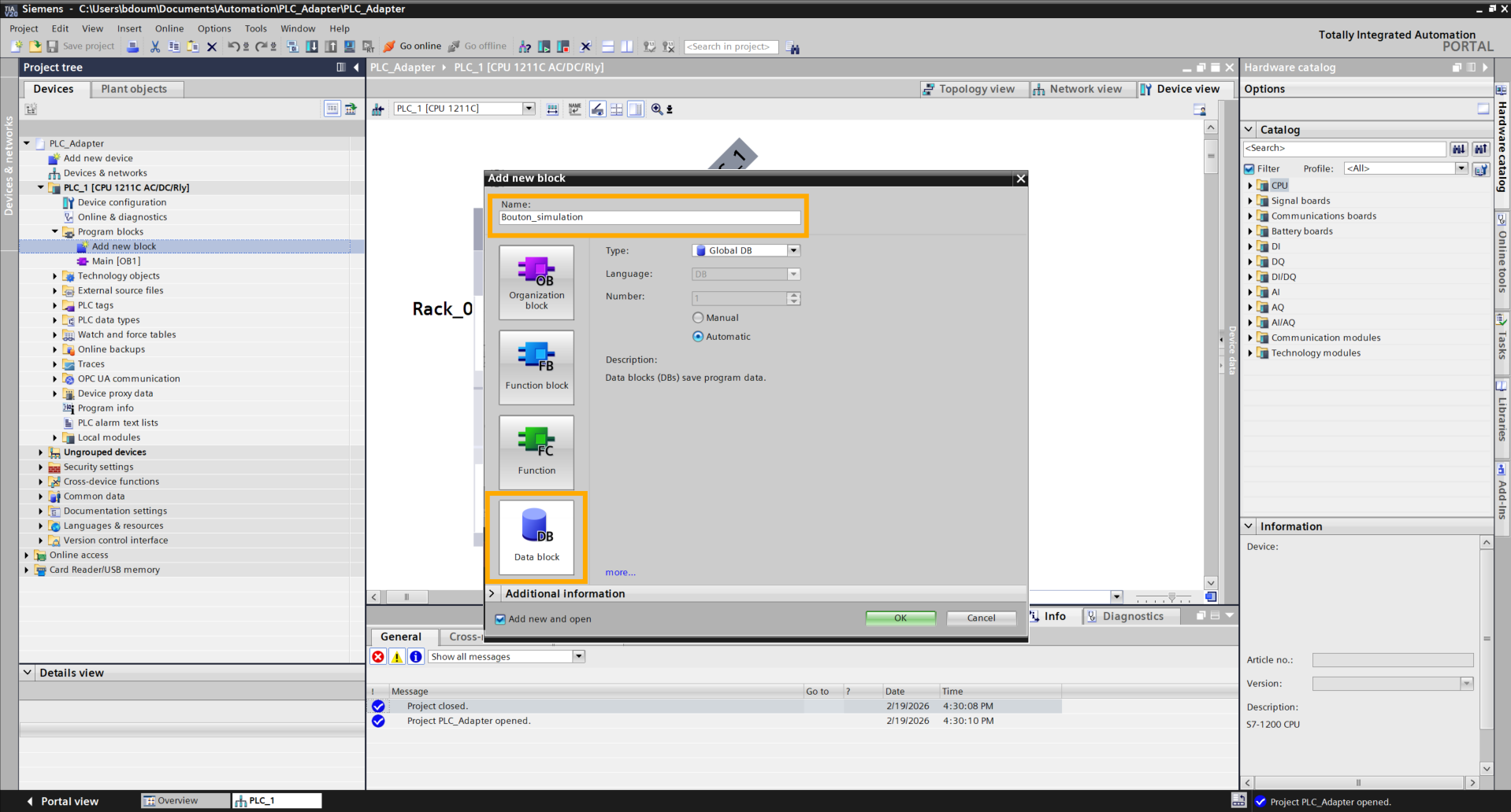
Click OK then enter the names of your choice for the three buttons (Button_1, Button_2, Button_3). To simulate a button press, the idea will be to switch the value present in the Start value column from False to True.
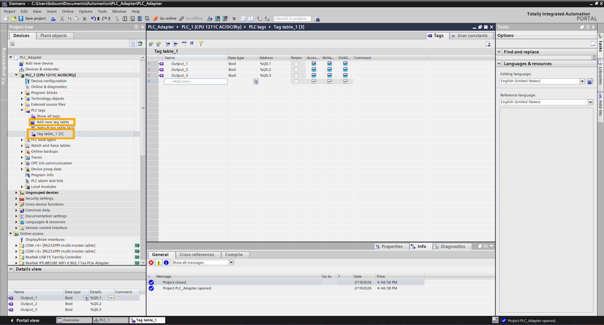
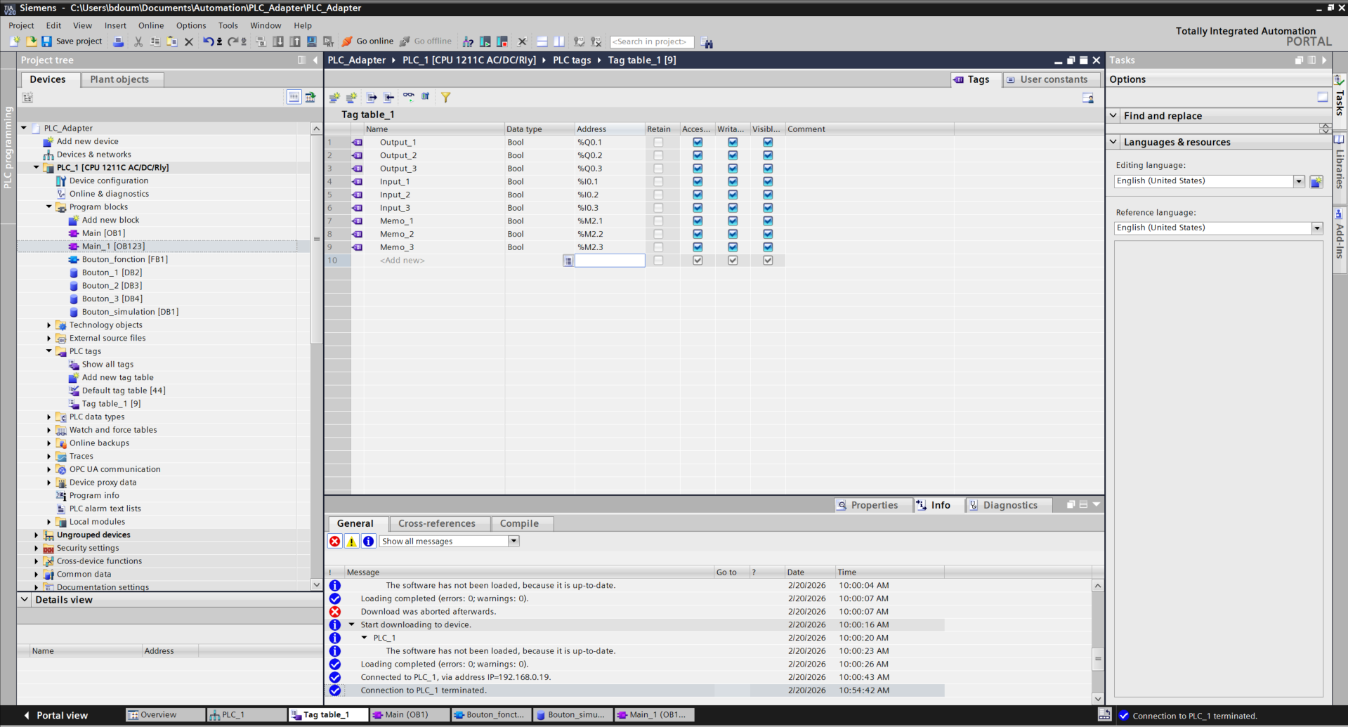
Next, we will create tags for our PLC outputs connected to the I/O Adapter. To do this, double-click on Add a new tag table. This will create a new table for the tags. Double-click on it and enter the names of your tags (your choice) as well as their respective addresses.
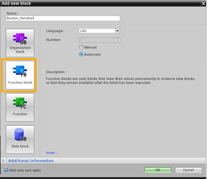
Then with all this, we will create a Function Block. This functionality allows us to have a general structure for our buttons and thus avoid cluttering our code. Click then on Add a new block. Go to the Function Block tab and choose a name. Click on OK.
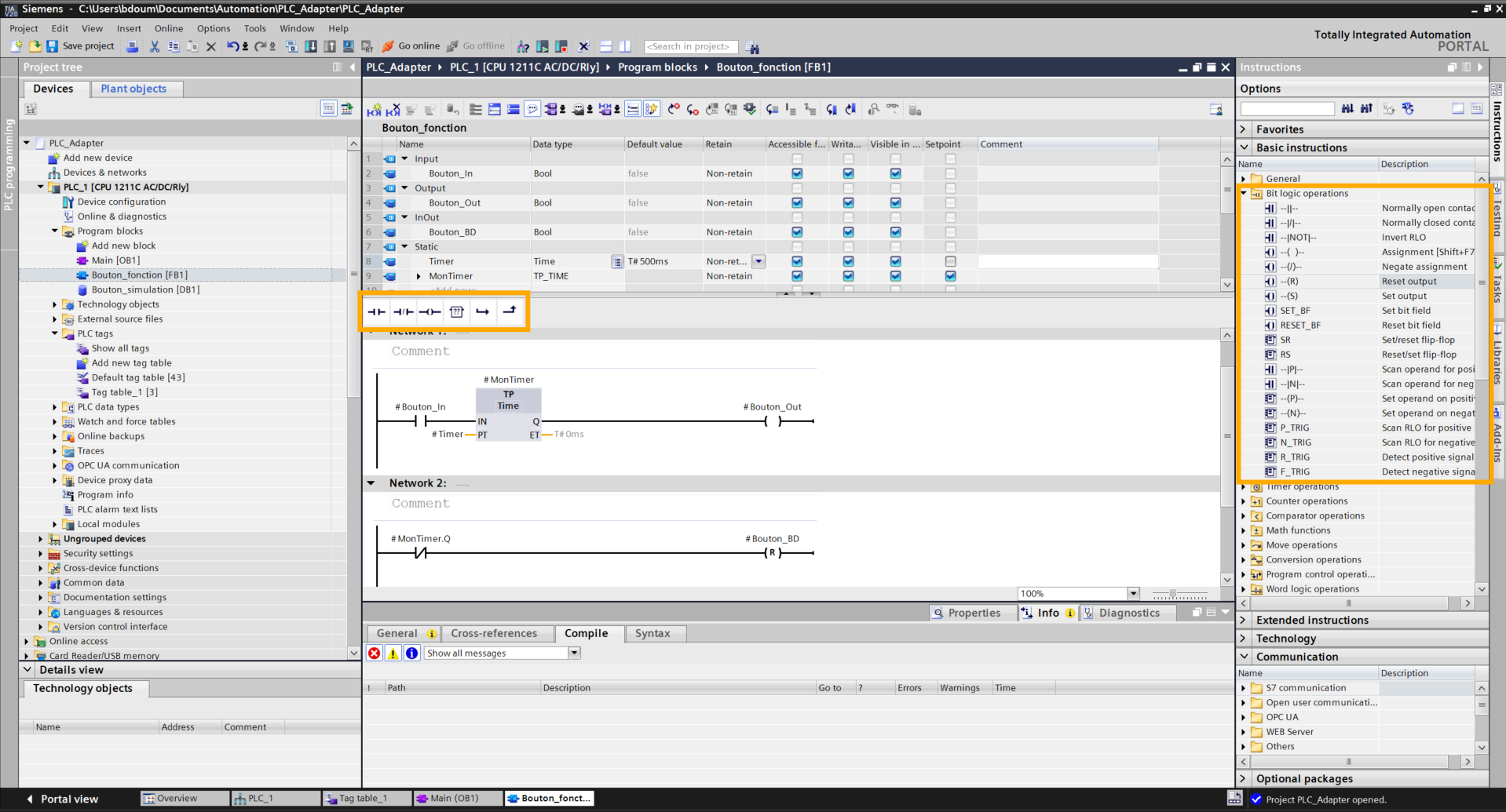
We will now program the behavior of our button. The objective is to generate a fleeting signal: as soon as the button switches to True, the program waits 500 ms before switching it back to False. This allows for faithful reproduction of the action of a user who presses and then releases a physical button.
The next step is to declare the variables necessary for controlling our button. Configure your variables ensuring their data type is Bool for logic states. For activation duration management, create a variable of type Time (Pulse Timer) and define the desired time as the default value.
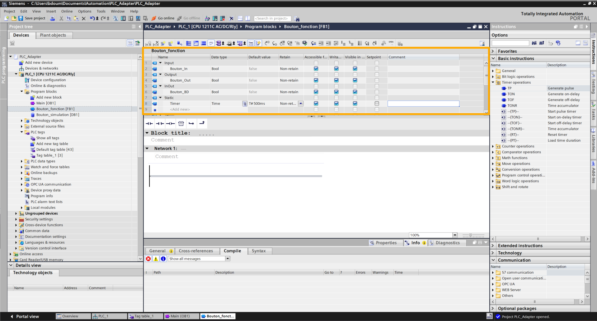
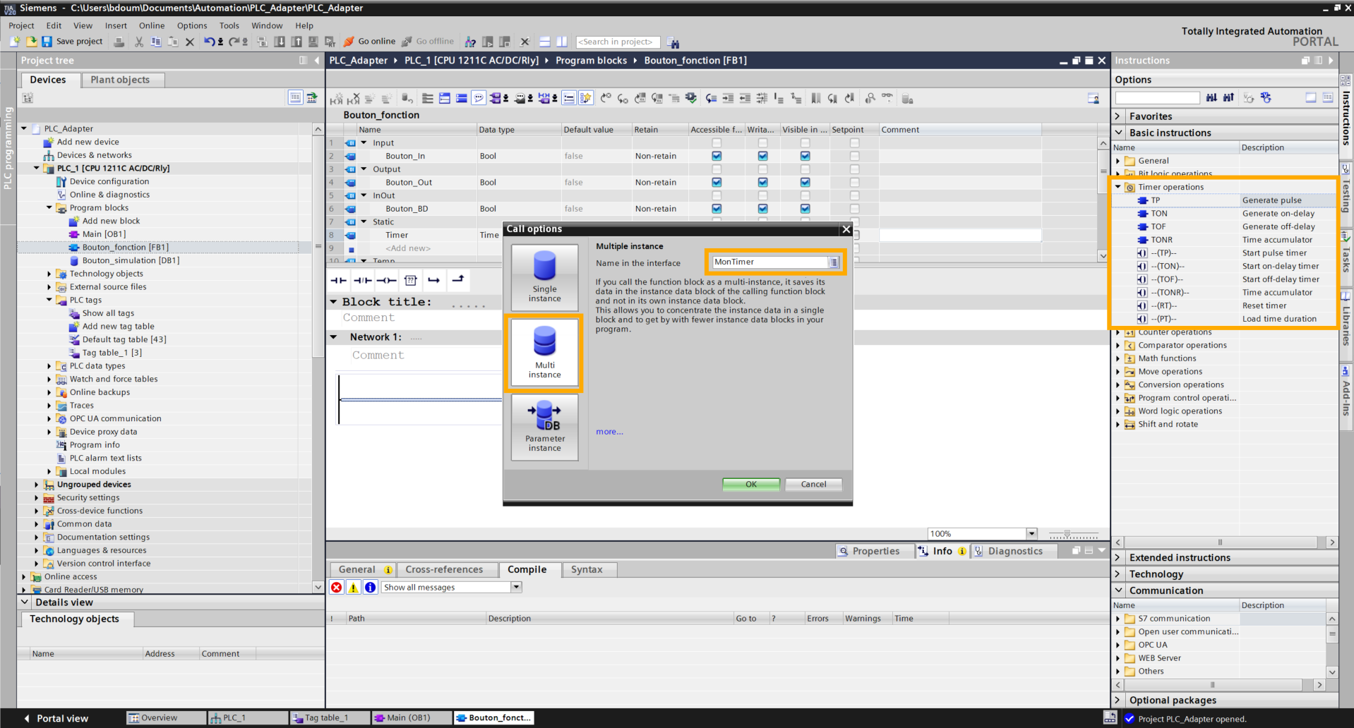
Next, add the TP block found in the Basic instructions → Timer operations. A window opens. In this window, choose a name (MonTimer for example) and select the Multi-instance option.
Add the blocks and connect the inputs and outputs in the same way as shown in the following image.
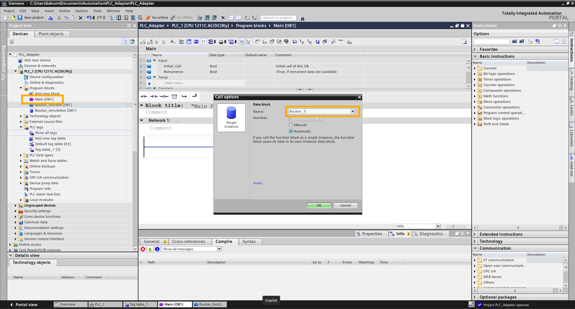
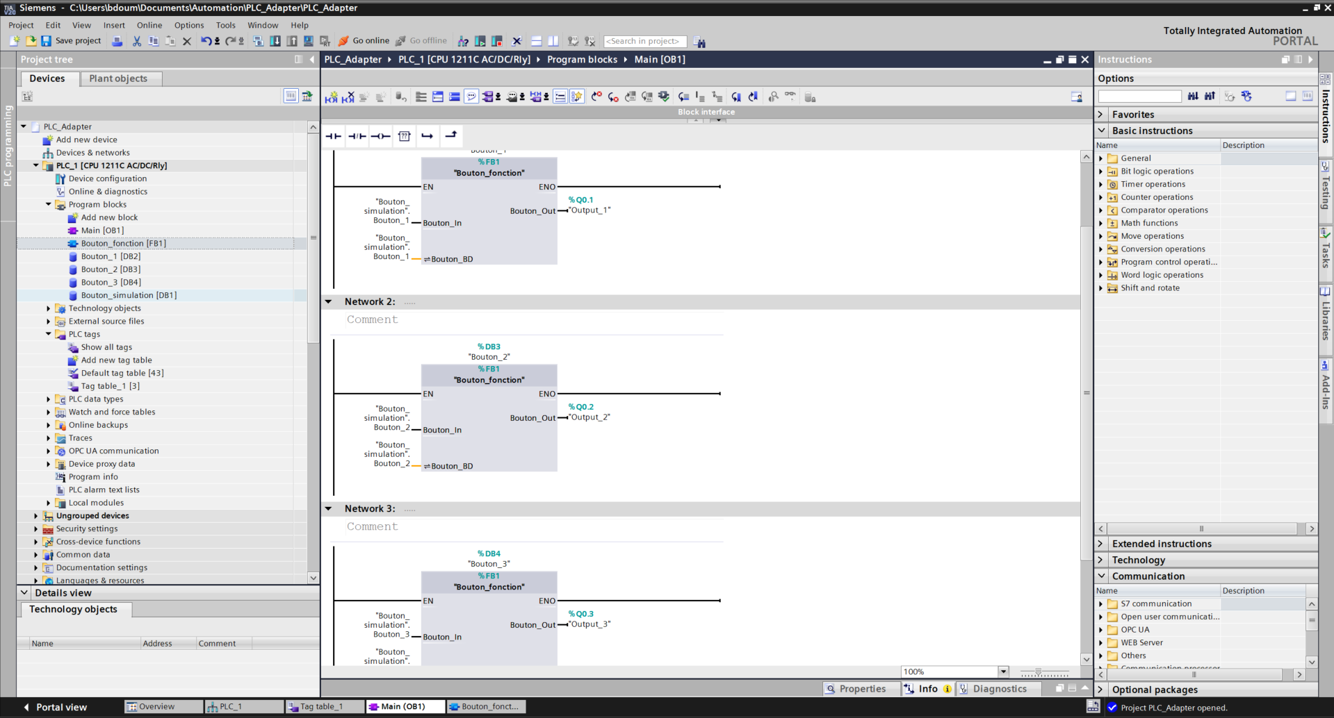
Go to the Main block (on the left) and drag and drop the function block onto the first rung. Give your first button a name.
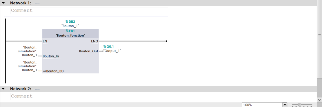
Connect the inputs and outputs in the same way as shown in the following image.
Repeat the same operation for the other buttons ensuring you select the correct corresponding inputs and outputs.
We will load all the modifications and programs created. For this, press the Download to device icon located at the top of the page and enter the security password.
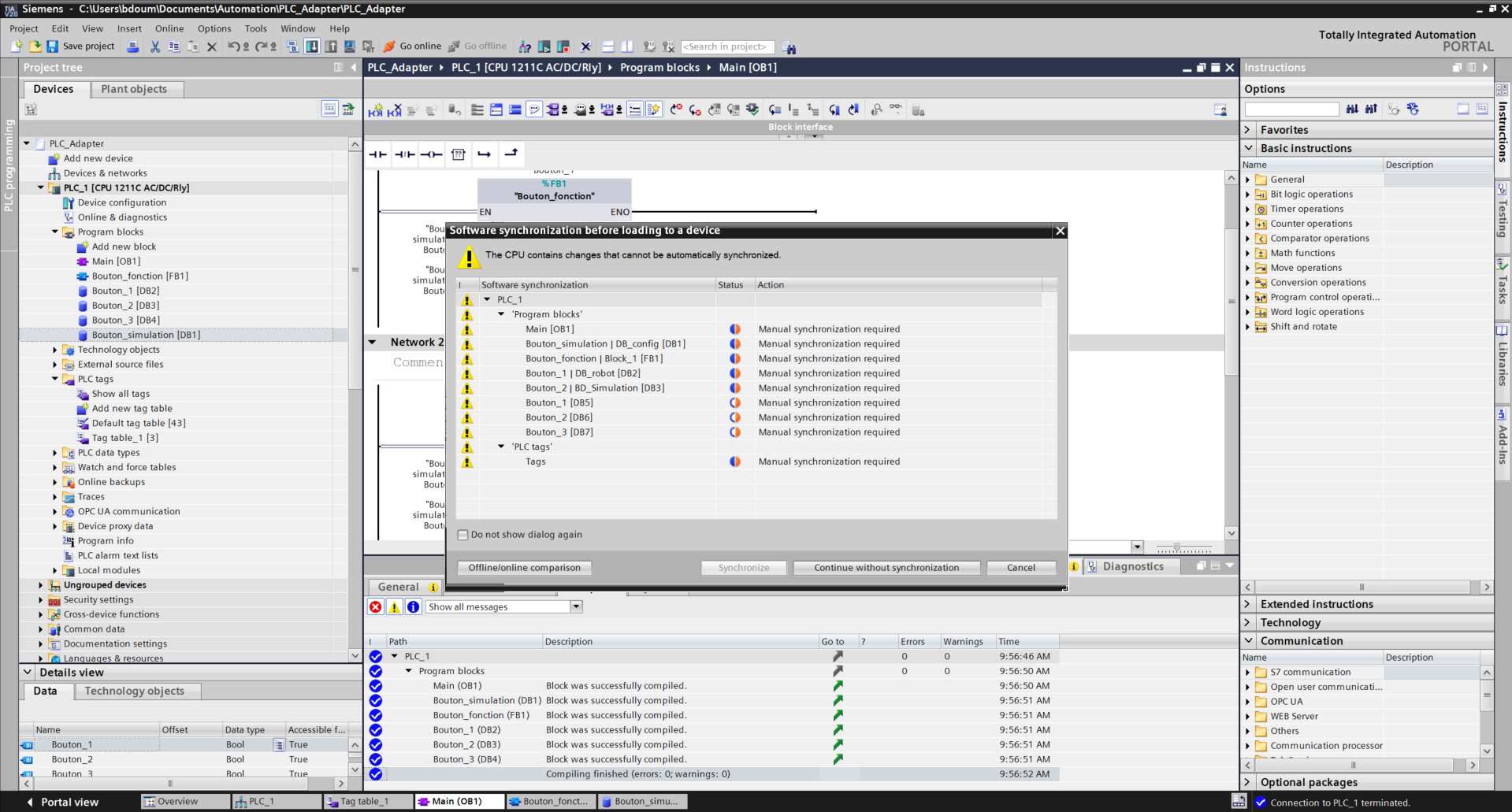
Press Continue without synchronisation and select Stop all in the red field bar, then Load.
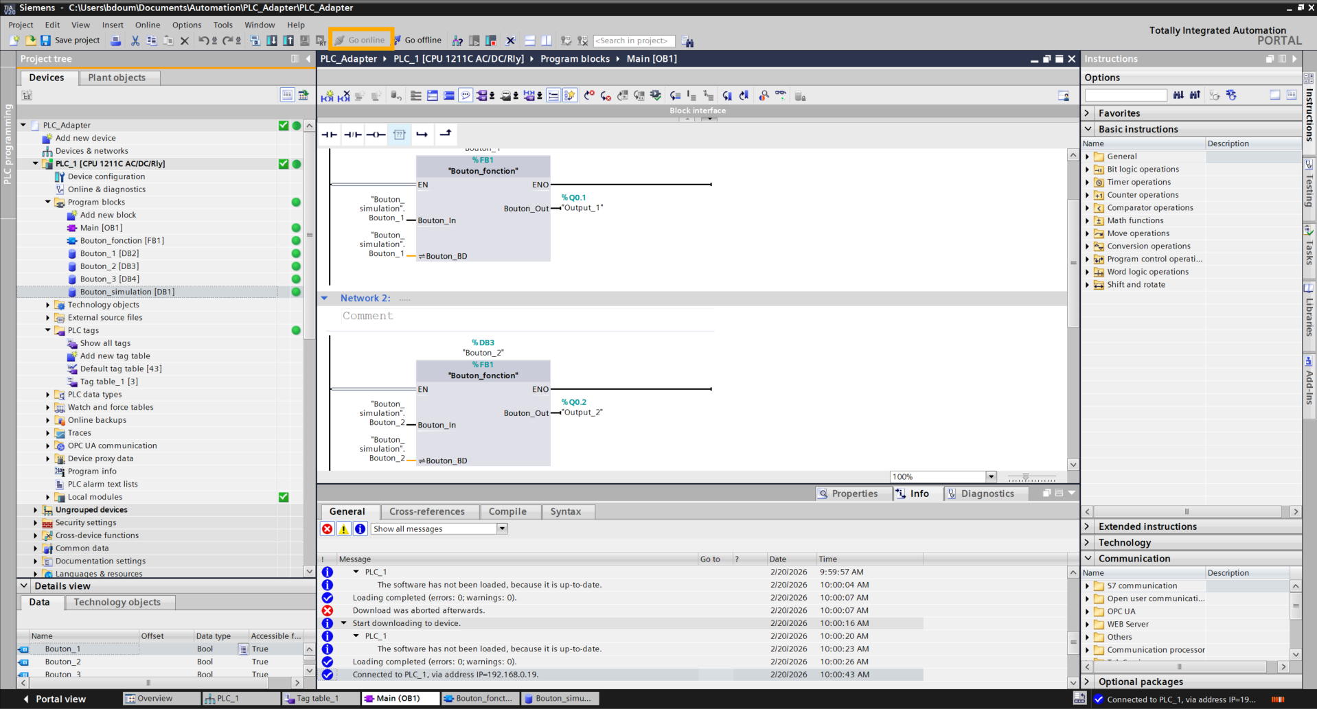
Click on Go online.
Go to the Bouton_simulation database tab, click on the glasses icon to activate dynamic monitoring.
To test the command, double-click on the False values: they will switch to True for half a second before resetting. Observe the activation of the connected output and hear the clicking of the relay on the PLC, confirming correct signal transmission.
Configuration on the TIA PORTAL side is now complete. It is time to switch to Niryo Studio to configure actions based on the commands sent.
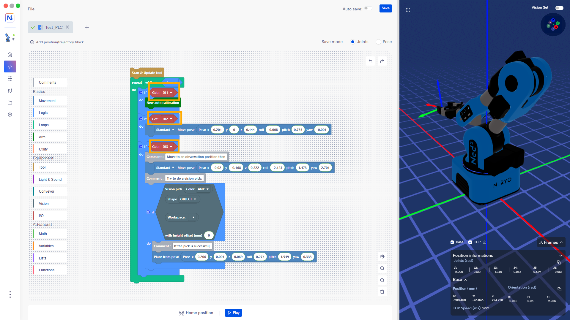
Programming on Niryo Studio
The code logic relies on monitoring digital signals. When an input is activated via the PLC, the robot executes the corresponding action (Calibration, Home or Vision Pick). These examples illustrate external control capabilities, but they can be replaced by any action supported by the robot. (Downloadable code here).
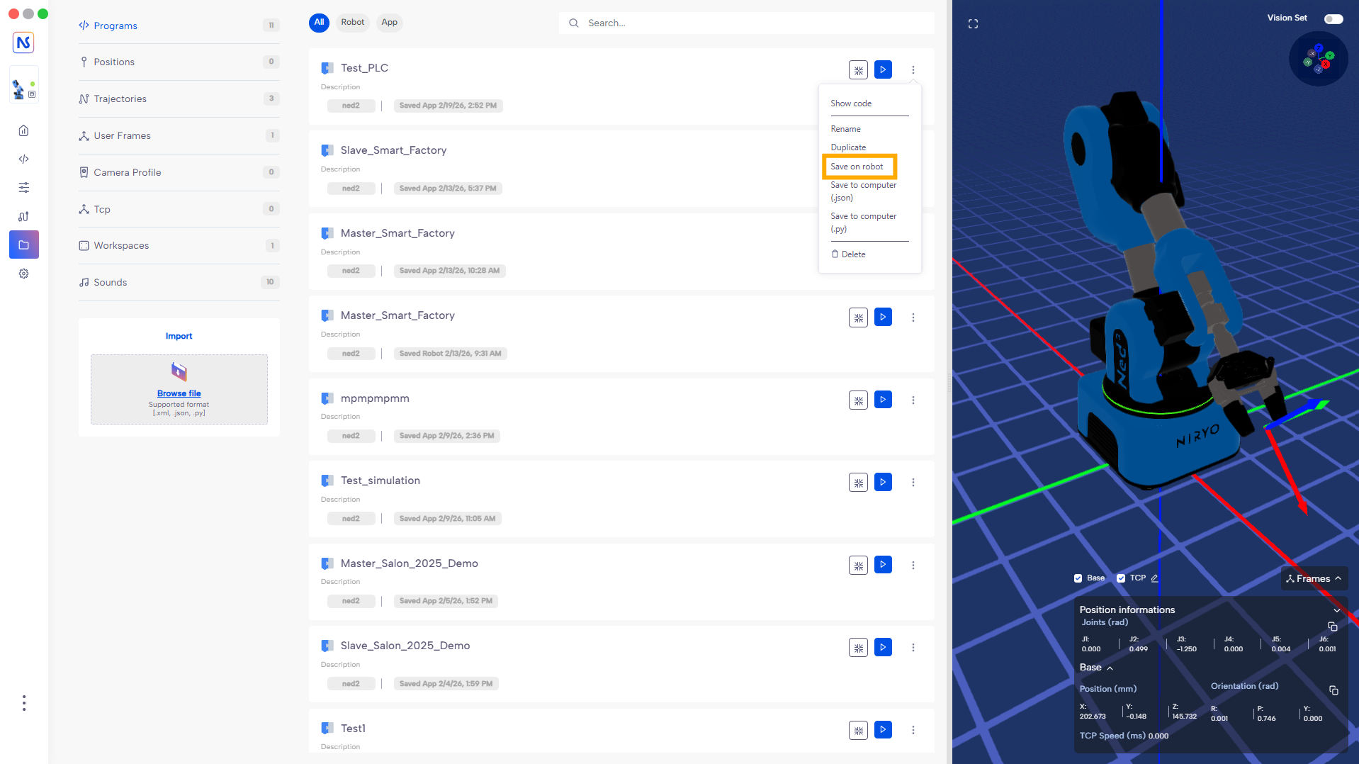
Save the code in the robot and select it in the Program autorun tab.
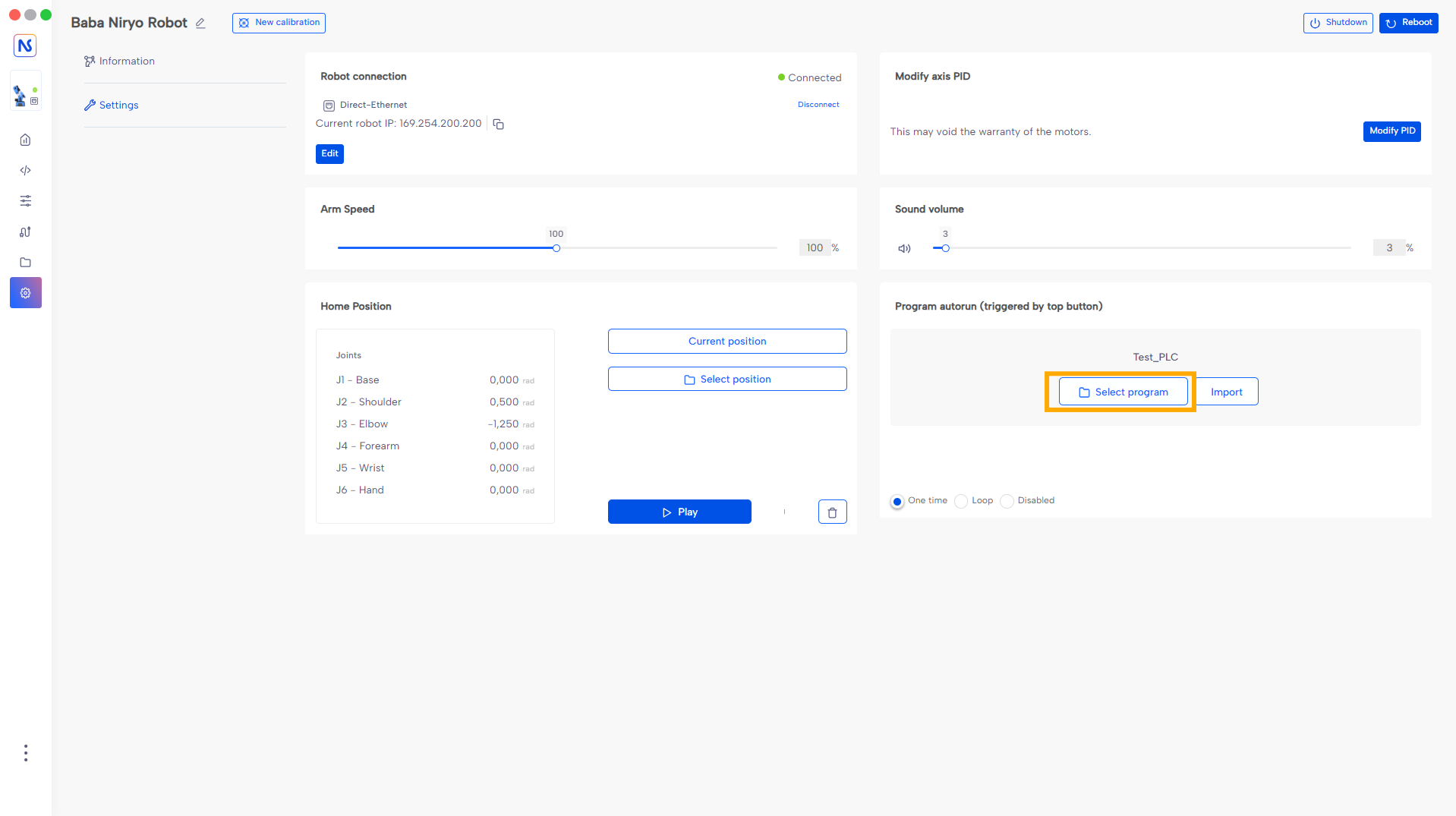
Launch the program by pressing the robot's Top button and take control! From now on, Ned2 control is done in real time thanks to the Siemens PLC interface.
Programming with PyNiryo
Similarly, the robot-side code can be done with PyNiryo using a Visual Studio type IDE. The code below performs the same function as the previous code. (Downloadable code here)
Using physical buttons
In the case of using physical buttons, the configuration on TIA PORTAL is much simpler.
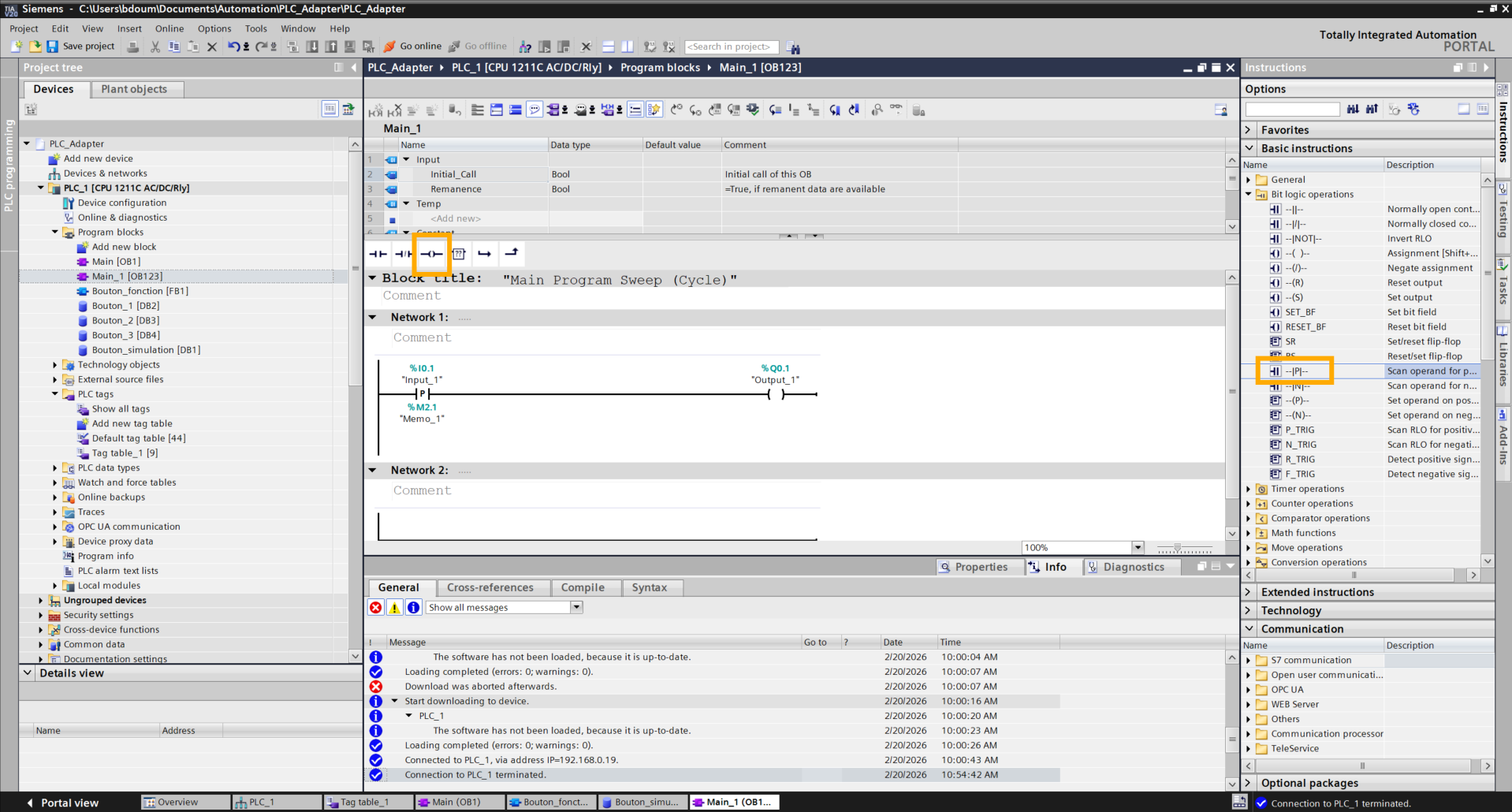
In the tag table (PLC Tags), create the inputs corresponding to the PLC's physical signals. Also add the state memories (markers) necessary for detecting rising edges for each control button.
In the Main block, create a Ladder rung for each button composed of a Positive Edge contact and a Coil. Connect the inputs and outputs in the same way as shown in the image.
Ensuring the robot-side code is still running, send commands by pressing the buttons connected to the PLC.