Controlling a Ned2/Ned3Pro via a Siemens PLC and TIA Portal V20 (Modbus TCP)
Interface configuration on TIA PORTAL
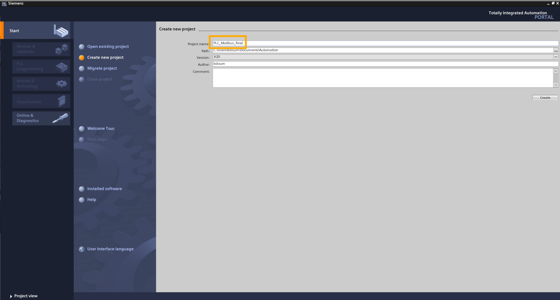
On the computer, create a new project on TIA PORTAL.
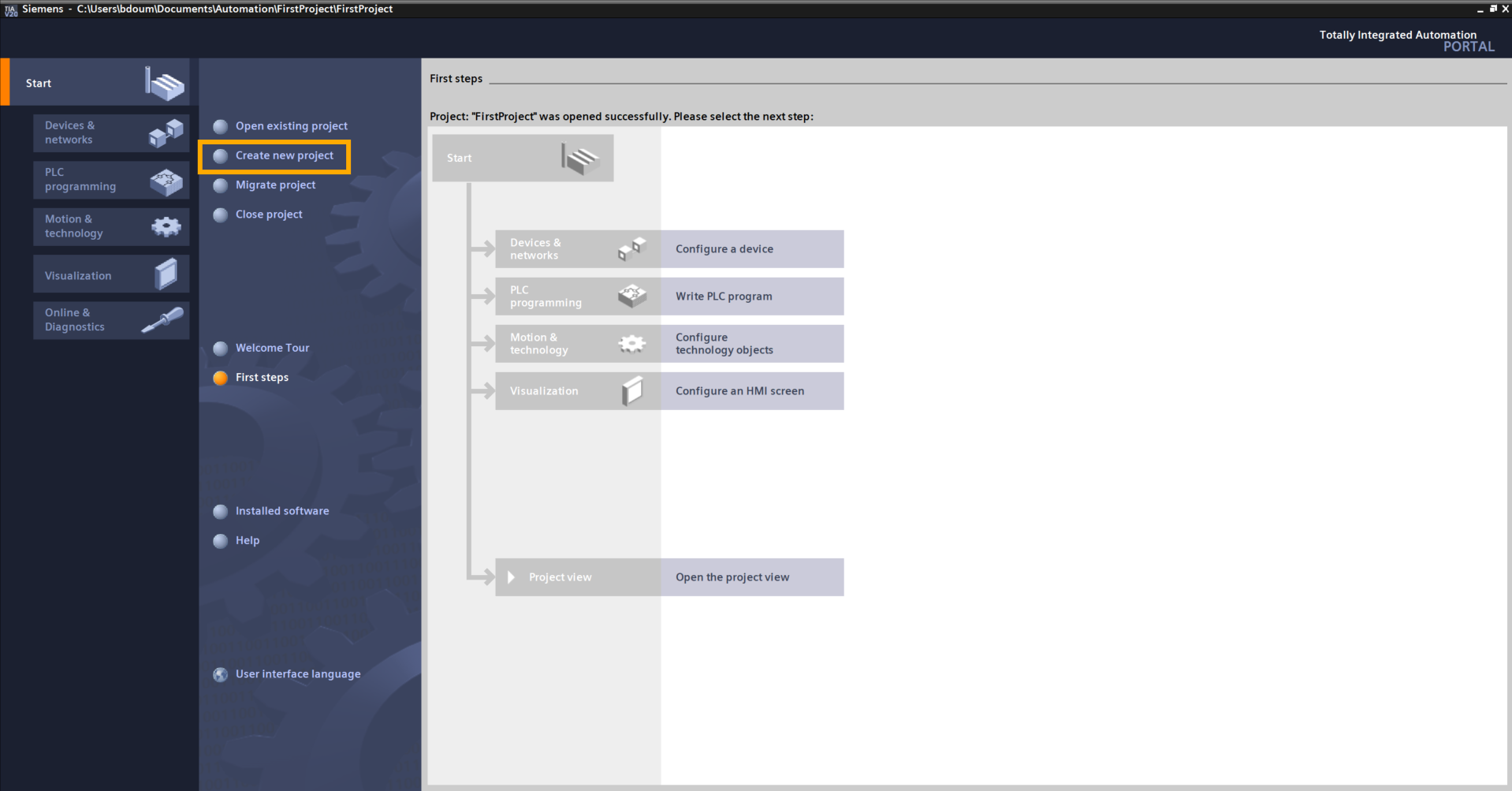
Name it as you wish. In our example, the project is named PLC_Modbus_final:
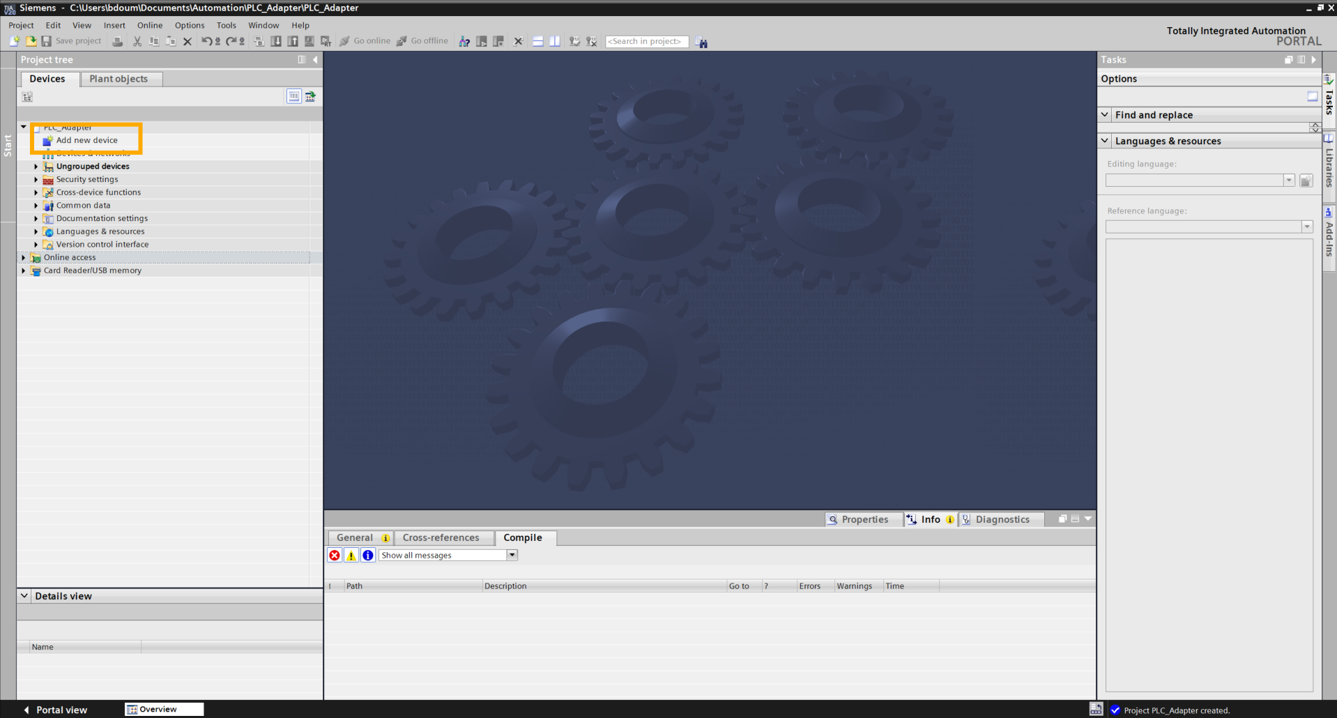
Click on Project view.
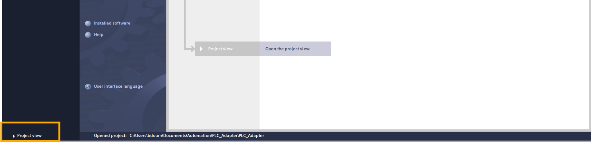
This should lead you to this interface. The next step is to add our PLC with its input and output modules.
To do this, double-click on Add device.
The following window appears.
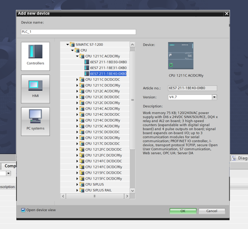
Select the PLC reference in the Controllers window.
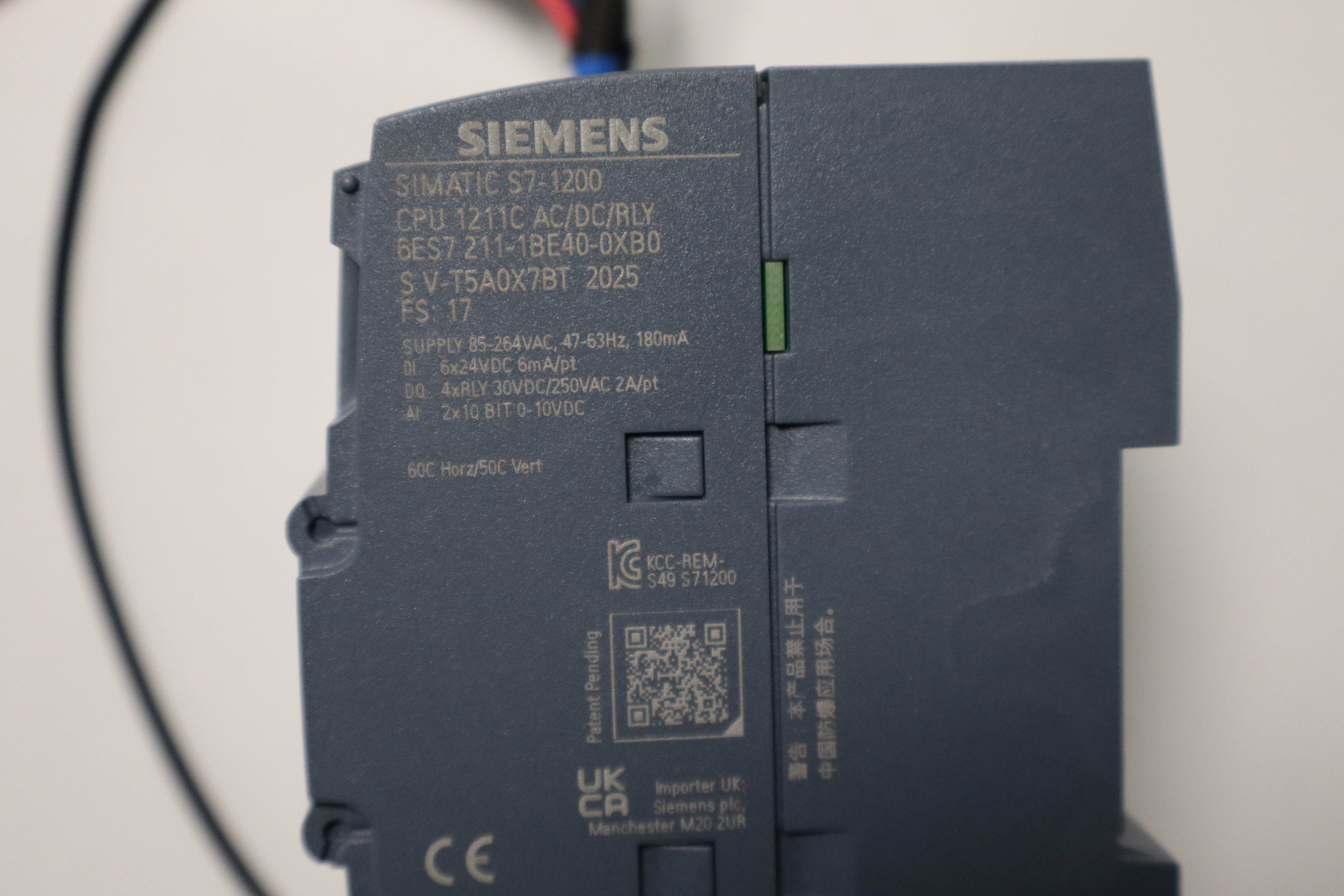
In our case: SIMATIC S7-1200 → CPU 1211 AC/DC/Rly → 6ES7 211-1BE40-0XB0. In case of doubt, the reference can be found on the PLC itself, as shown in the following image.
Click OK.
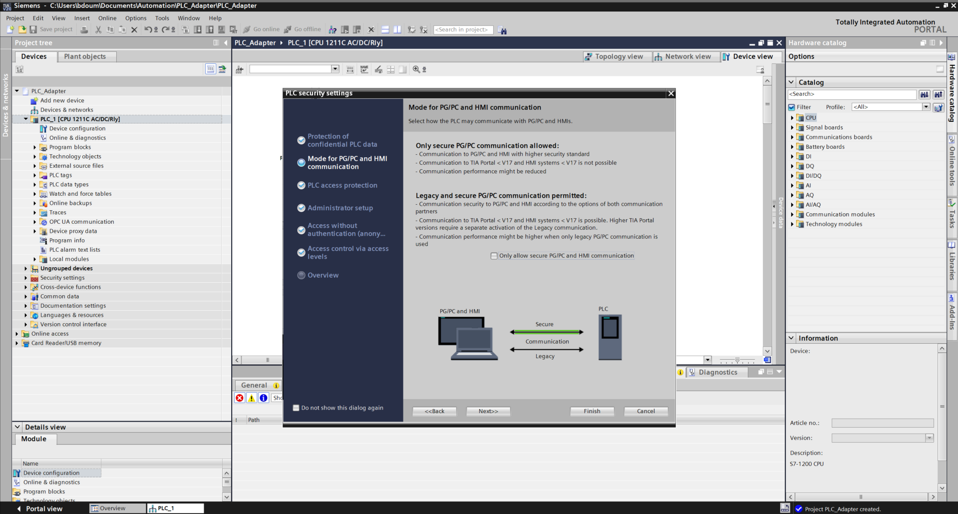
A window suddenly appears. It allows you to define the security settings when connecting with the PLC.
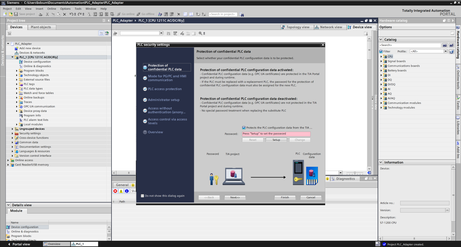
For the purposes of this tutorial, uncheck the box Protects the PLC… Press Next. Do the same on the next page to obtain this type of result.
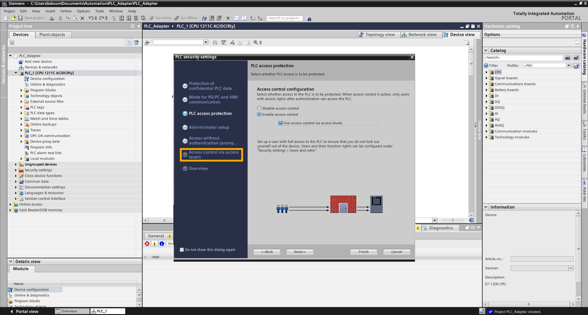
On the next page, select the option Use access control via access levels. Then click directly on the tab Access control via access levels.
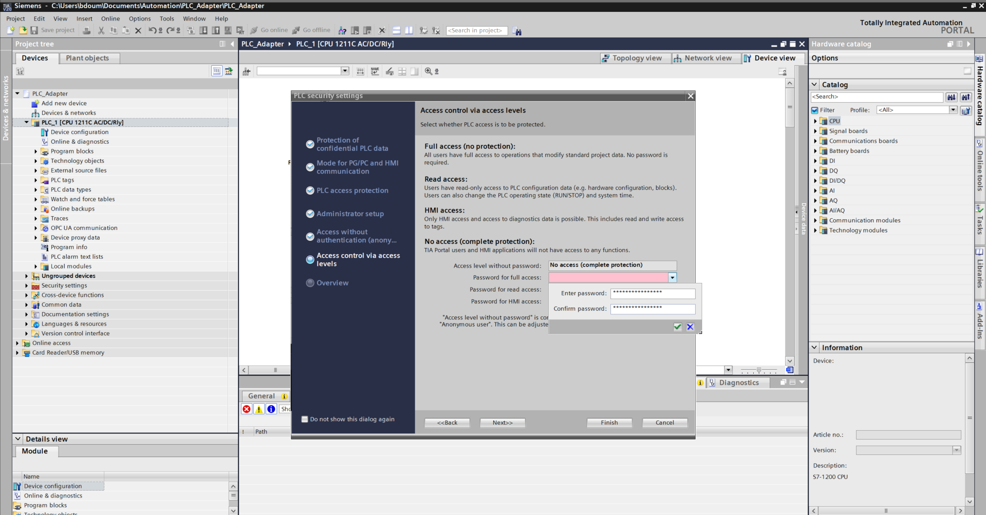
Click on the red field bar at the Full access configuration level and choose a password considering the requested requirements.
On the Overview tab, check the following information:
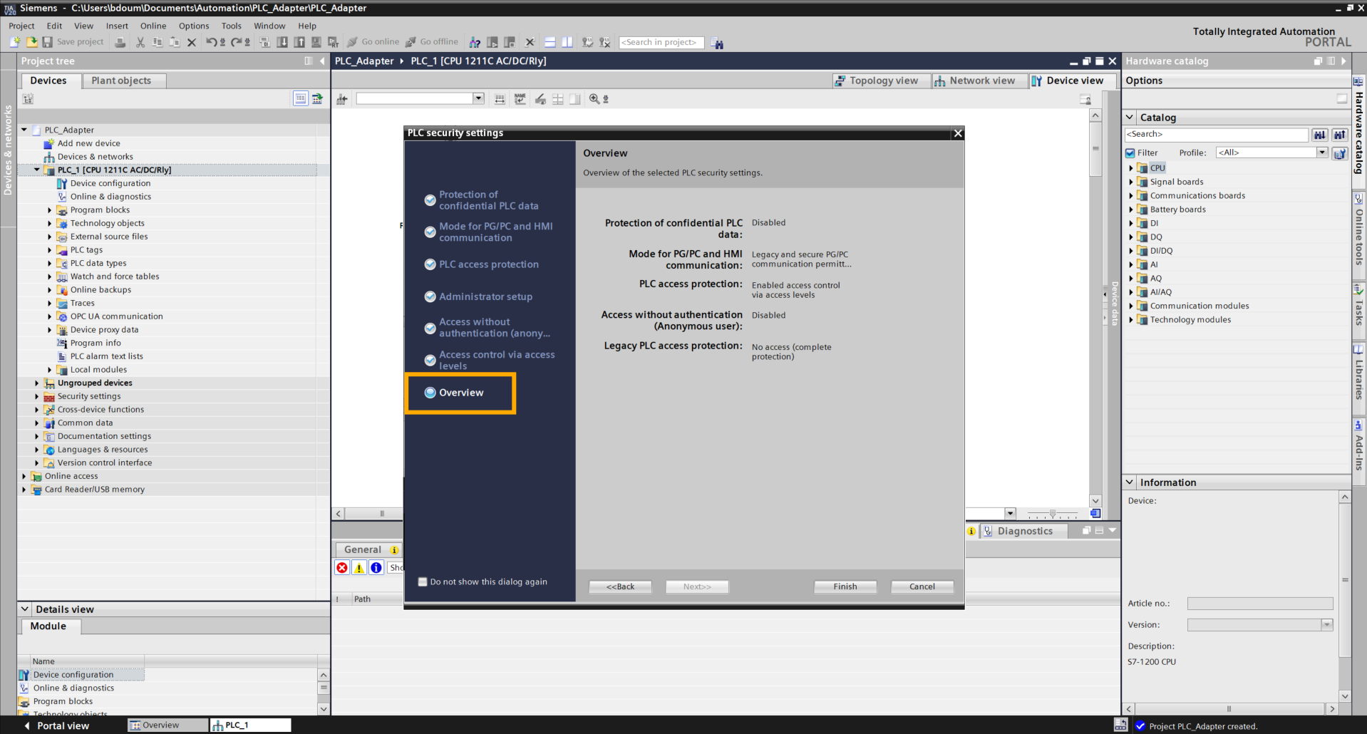
Click on Finish to complete the configuration.
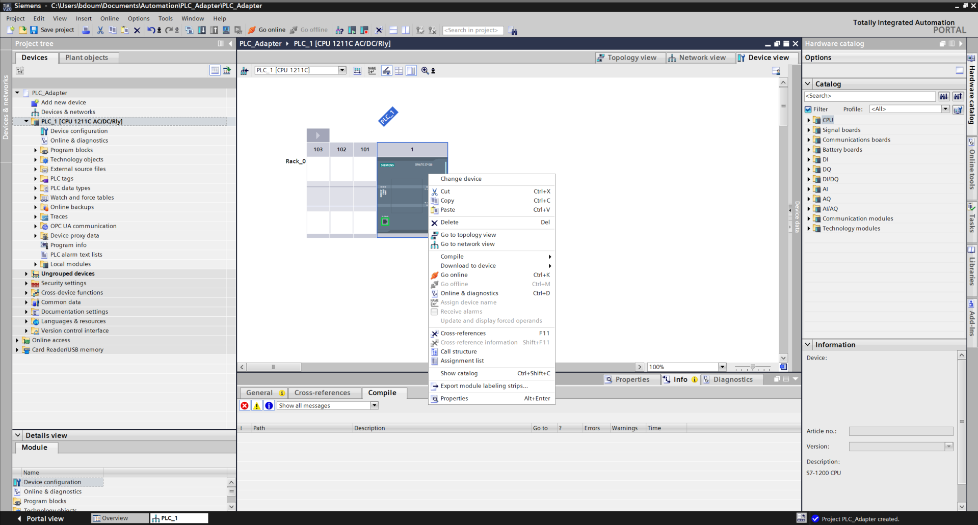
Right-click on the PLC, then go to Properties.
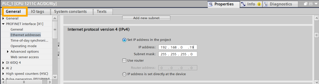
Go to the General tab → PROFINET Interface[X1] → Ethernet addresses → Internet protocol version 4(IPv4).
Enter the available PLC IP address as shown in the following image. In our example, the IP address is 192.168.0.19.
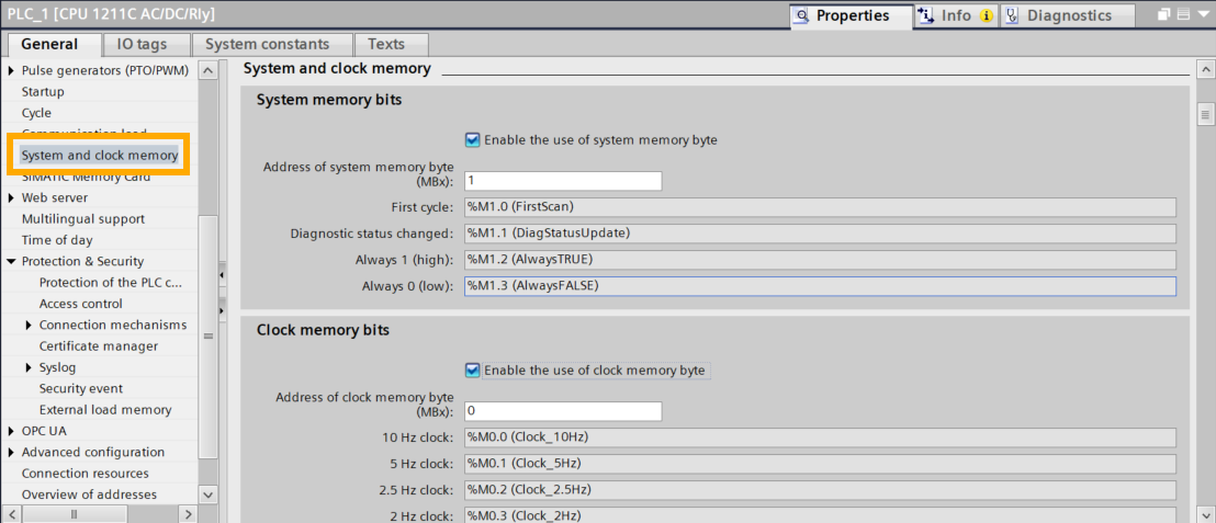
Next, click on System and Clock Memory. Check the two following boxes.
Next, we will proceed with loading the program into the PLC.
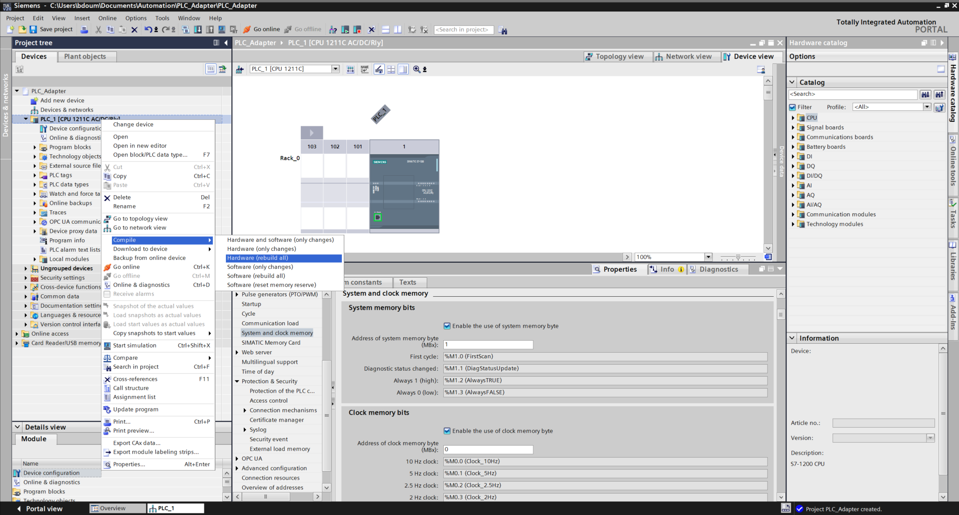
Start with the Hardware compilation:
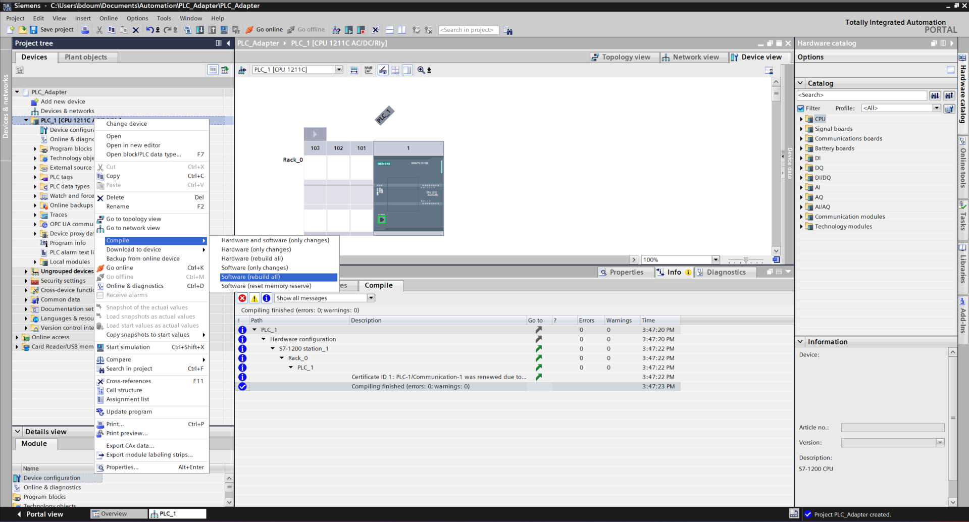
Right-click on the global folder of PLC_1, then go to Compile → Hardware (rebuild All).
Do the same for the software.
It is time to proceed with loading the program. Right-click and go to Download to device→ Hardware configuration.
An interface like this one should appear. After a certain time, the PLC is detected. If the search did not start, click on Start Search.
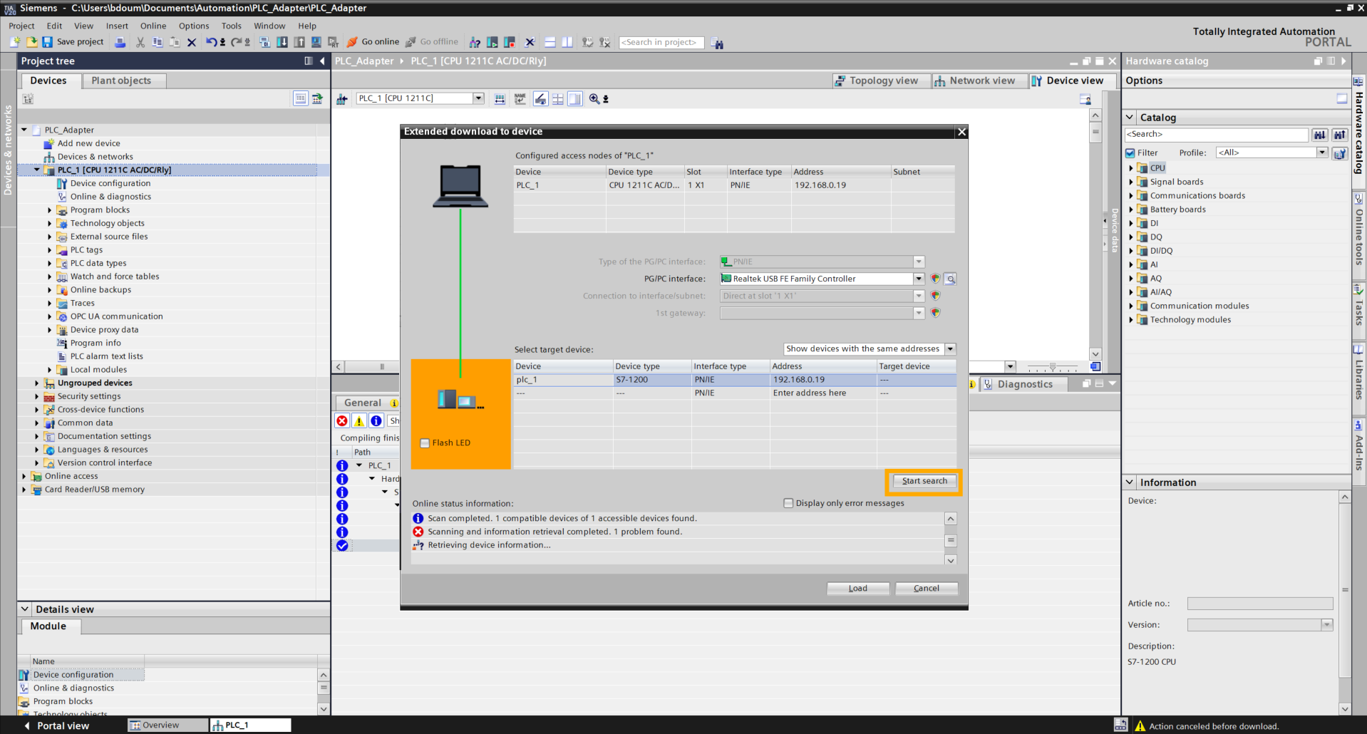
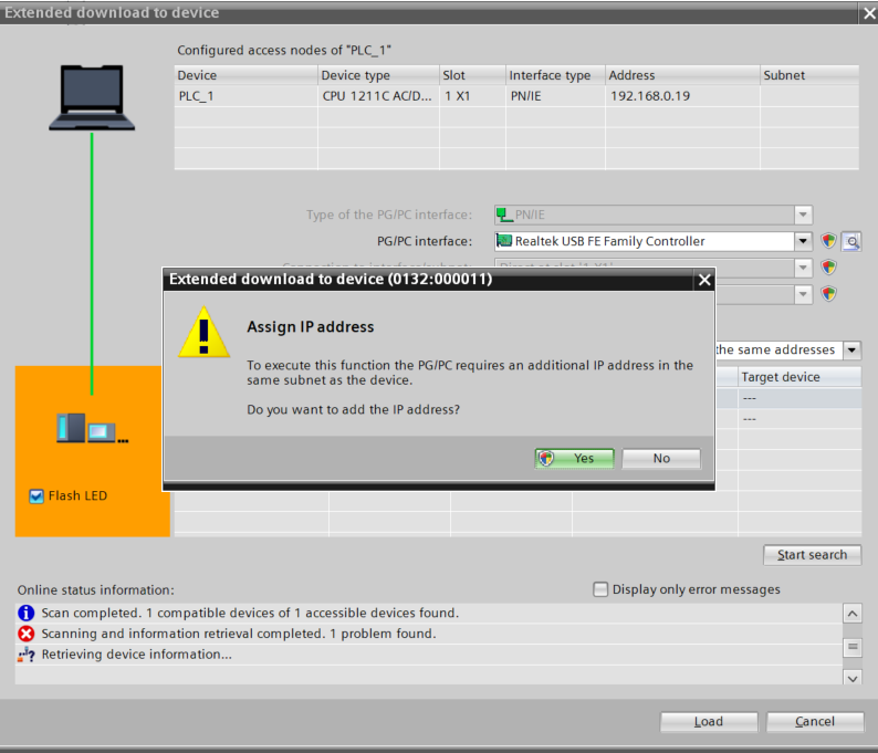
Subsequently, check the Flash LED box, then click on Load. Click Yes at the message level.
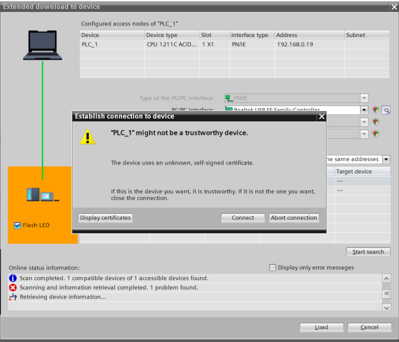
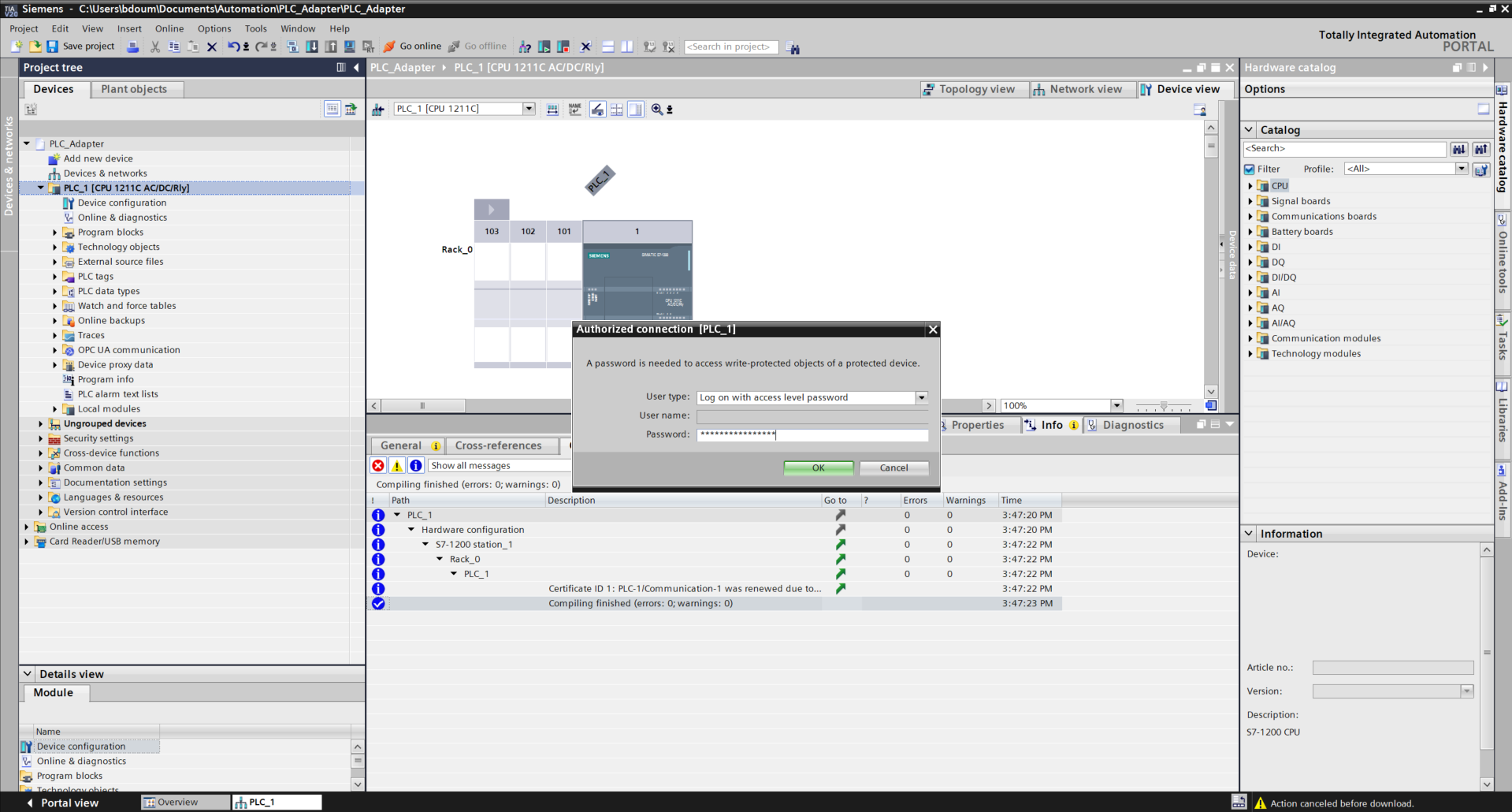
Click on Connect.
Enter the password defined previously during the security configuration.
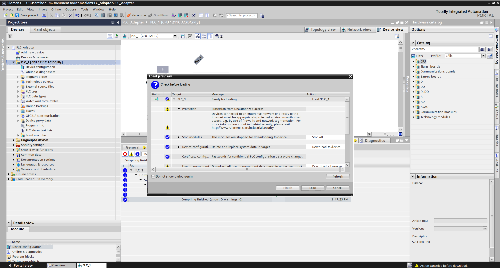
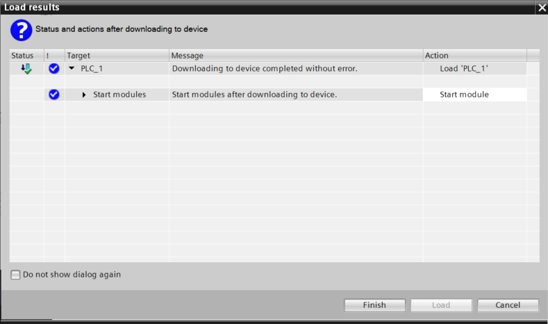
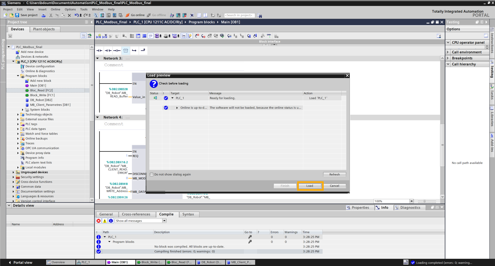
By clicking OK, the following window opens. Click on Load and on Finish.
Click on Go online to verify if the connection is correctly defined.
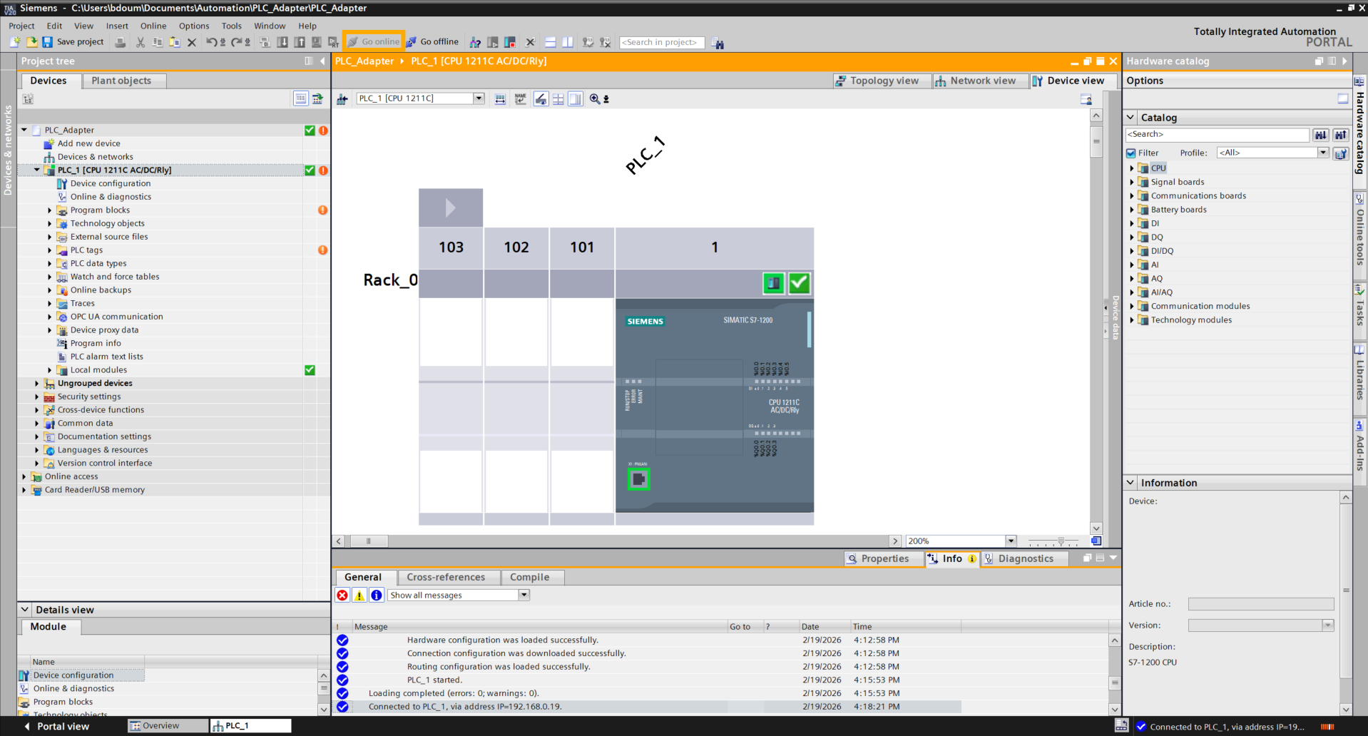
Then click on Go offline.
In this step, we will configure the Modbus client of the PLC.
To do this, we will create a database that will contain the variables representing the buttons. Double-click on Add a new block.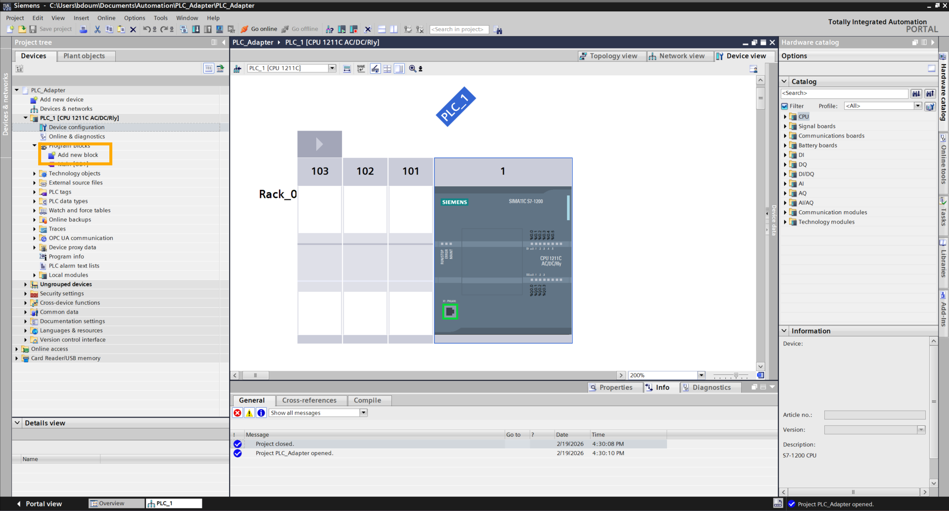
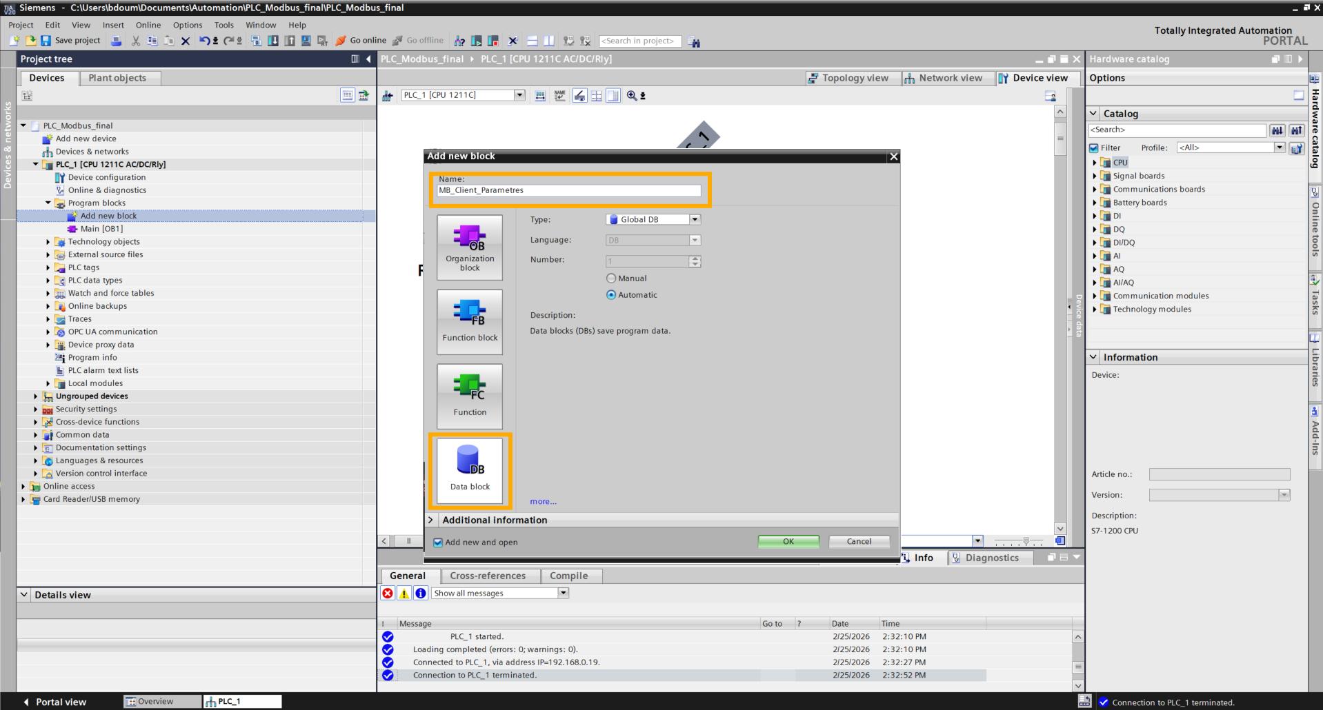
A window like this one appears. Go to the Data block tab and choose a name. For the example, the chosen name is MB_Client_Parametres.
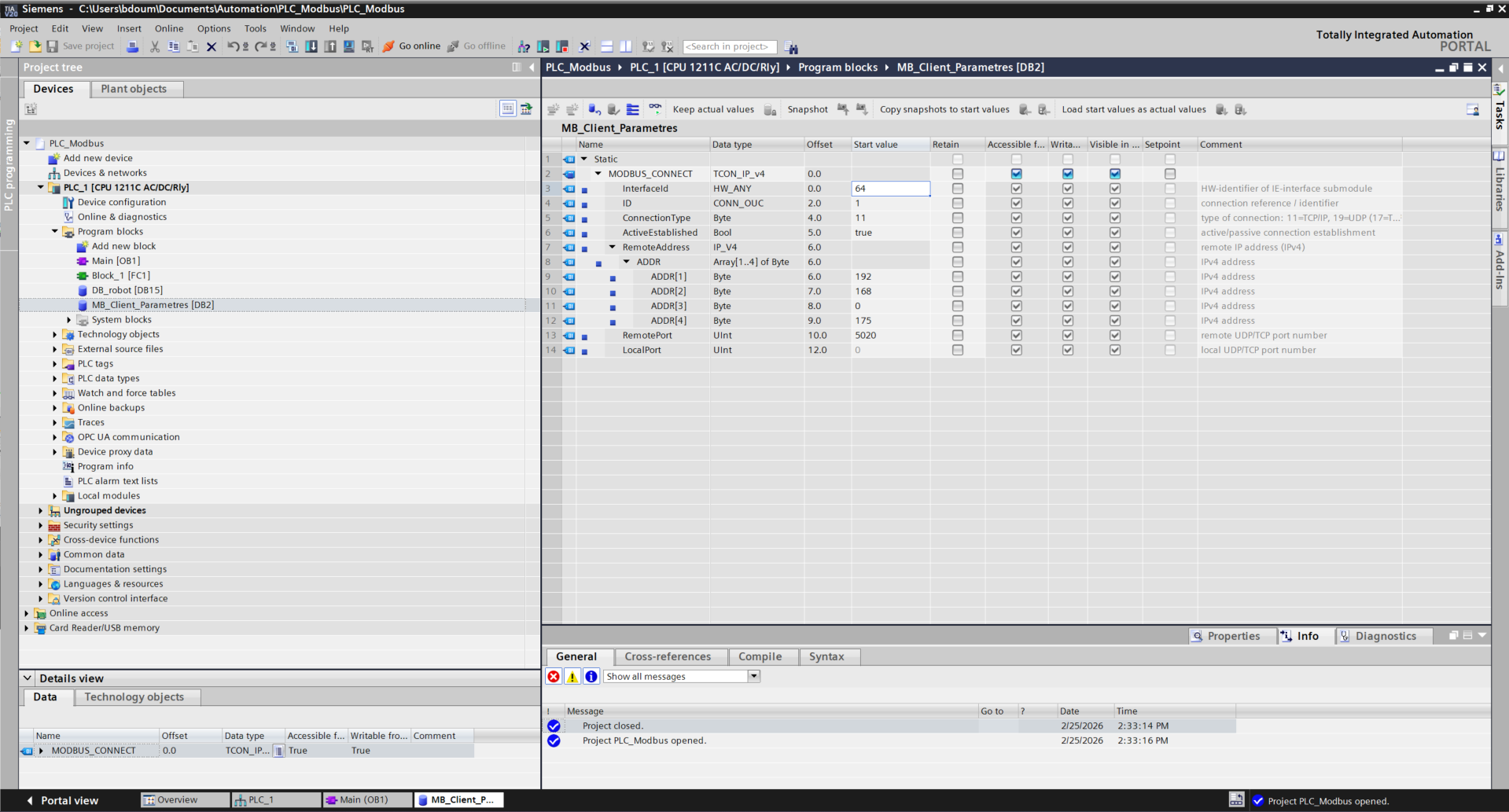
Add the MODBUS_CONNECT variable of type TCON_IP_v4 and expand this variable. Fill in the different parameters and for the ADDR part with the robot's IP address as in the image above. Adapt the IP address to your Ned2 configuration. The best is to define a static address as follows: follow the tutorial to define the static IP address here.
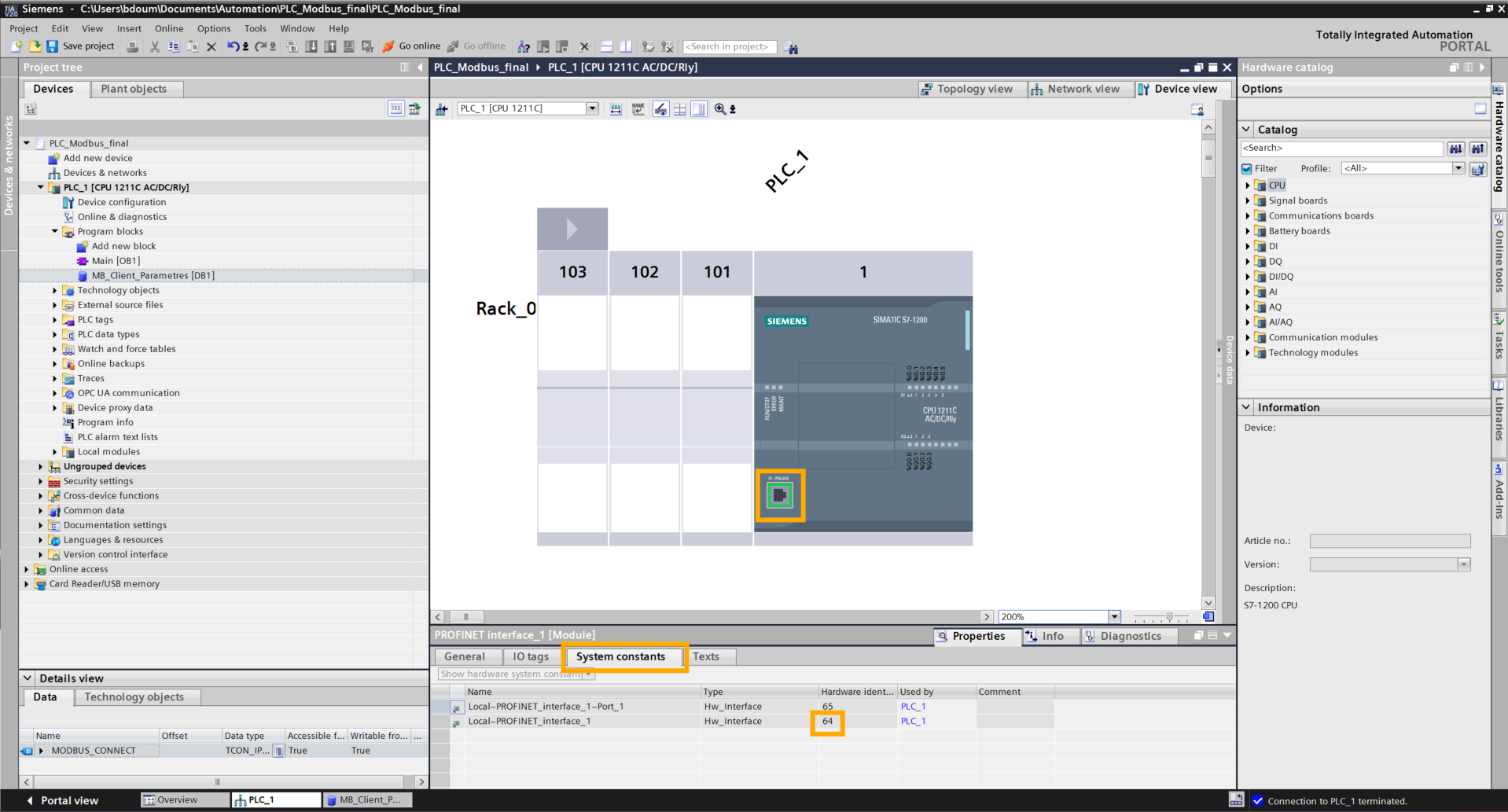
For the InterfaceId parameter, check the interface number by double-clicking on the Ethernet port then by clicking on System constants.
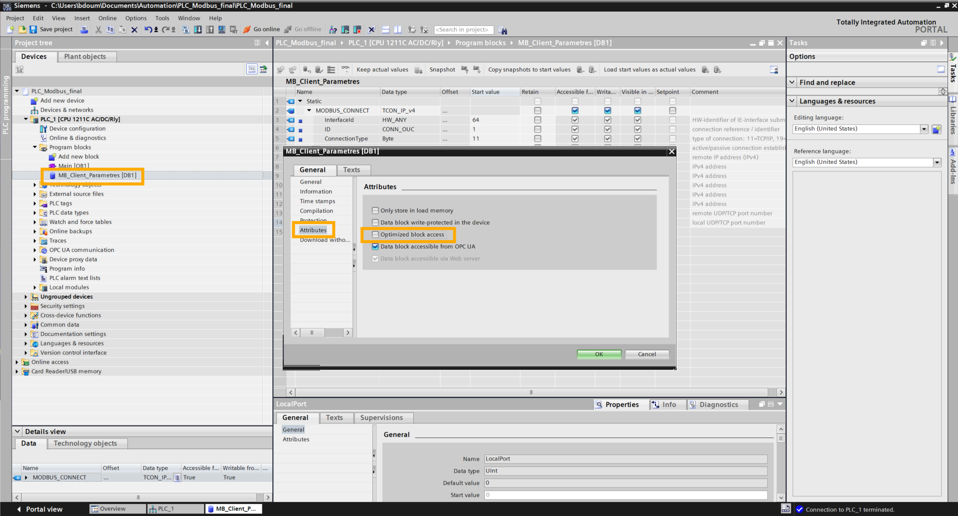
Then right-click on MB_Client_Parametres → Properties → Attributes, then uncheck "Optimized block access".
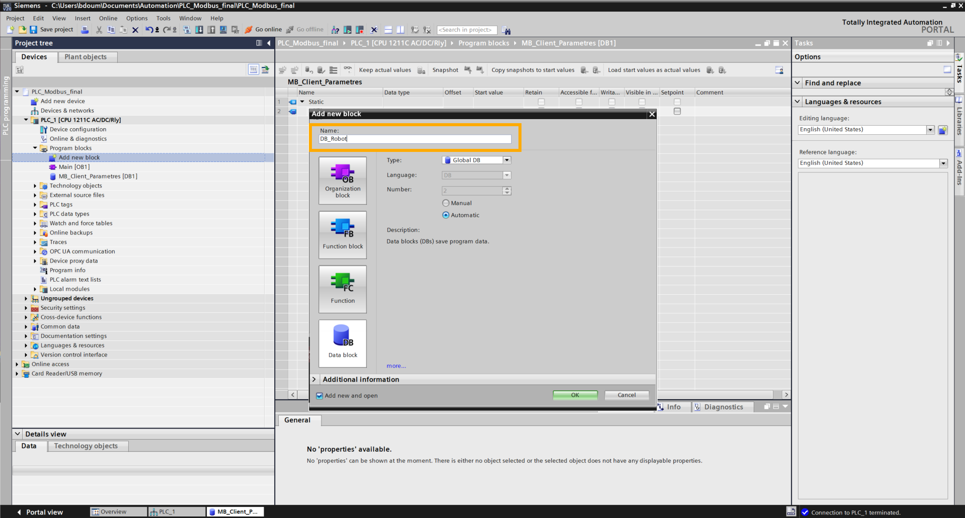
Create a new database named DB_robot.
In the same way, right-click on DB_Robot → Properties → Attributes then uncheck "Optimized block access".
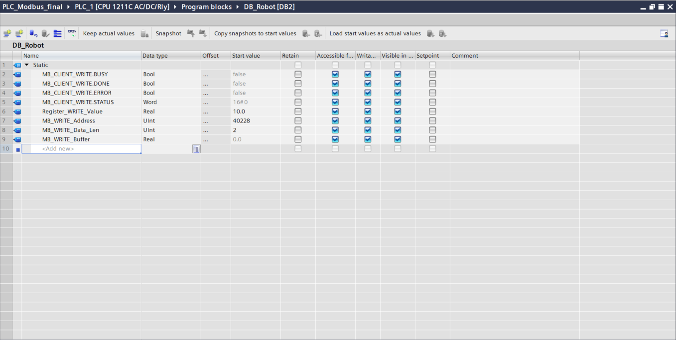
Add these variables:
-
MB_CLIENT_WRITE.BUSY (Bool)
- MB_CLIENT_WRITE.DONE (Bool)
- MB_CLIENT_WRITE.ERROR (Bool)
- MB_CLIENT_WRITE.STATUS (Word)
-
Register_WRITE_Value (Real): value that will be sent to the robot.
-
MB_WRITE_Address (UInt): to dynamically change the value register. To choose the address, refer to the Modbus documentation from Niryo.
-
MB_WRITE_Data_Len (UInt): to change the size of the data sent.
-
MB_WRITE_Buffer (Real): variable containing the value.
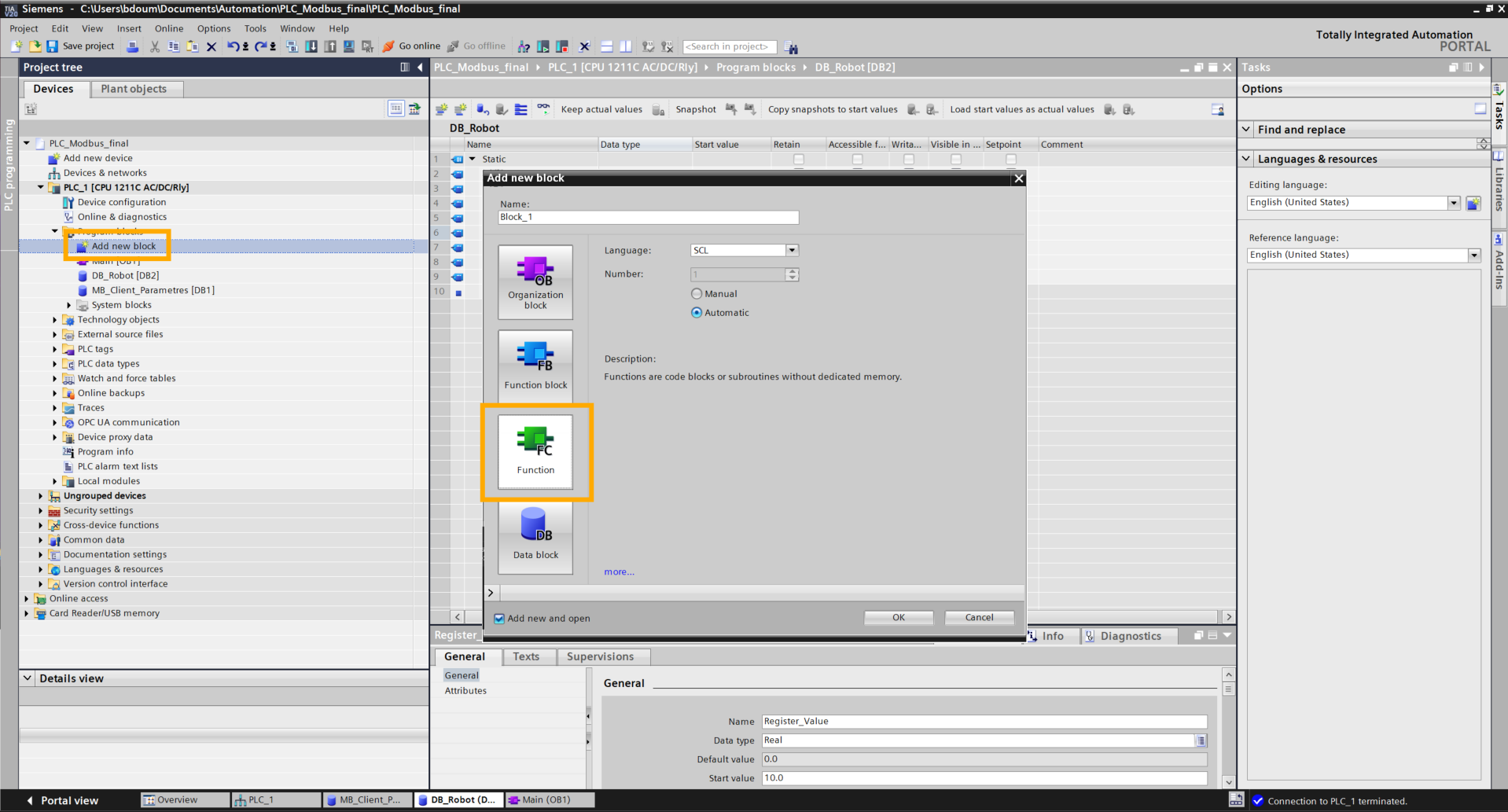
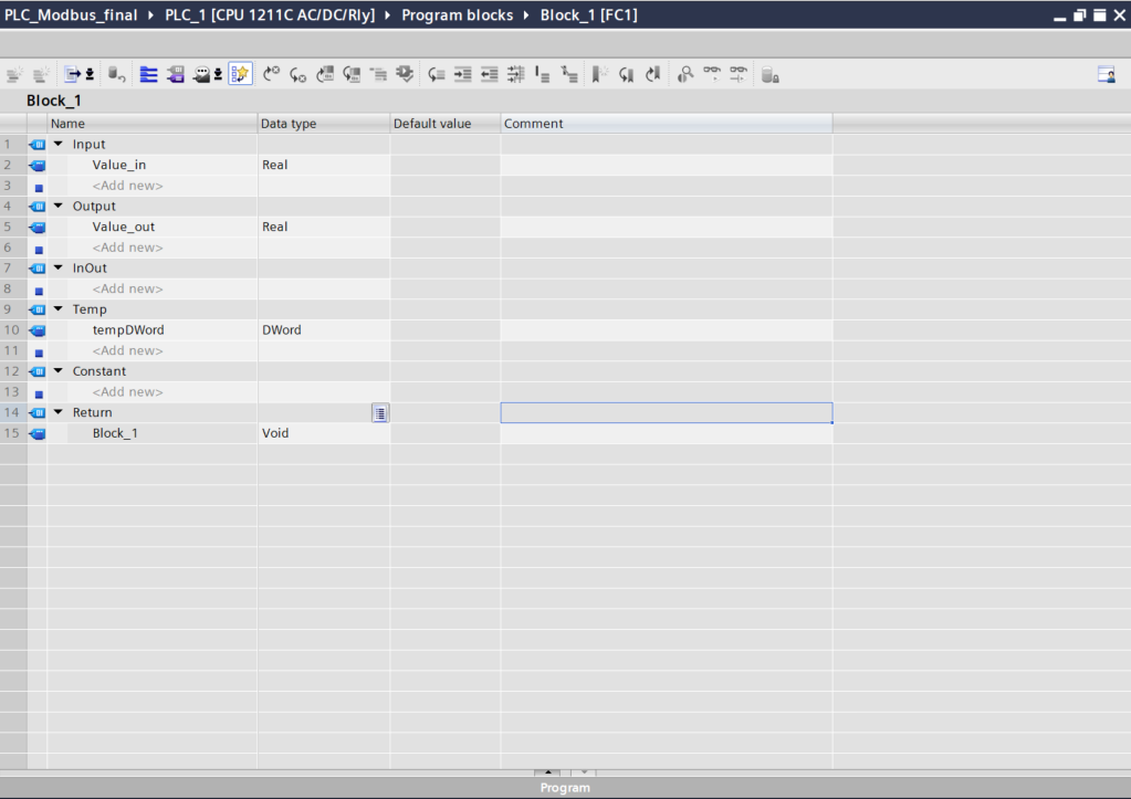
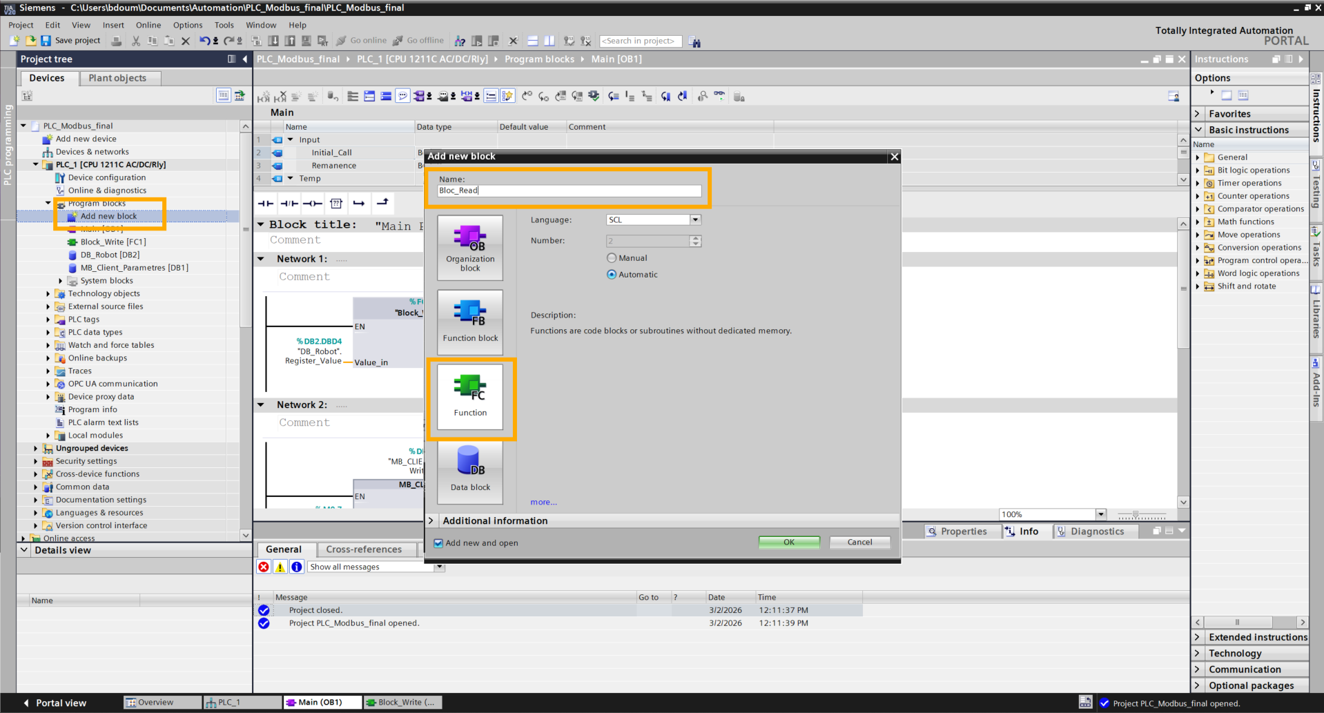
Create a function by clicking on Add new block. Choose a name (Block_Write).
Add the following variables:
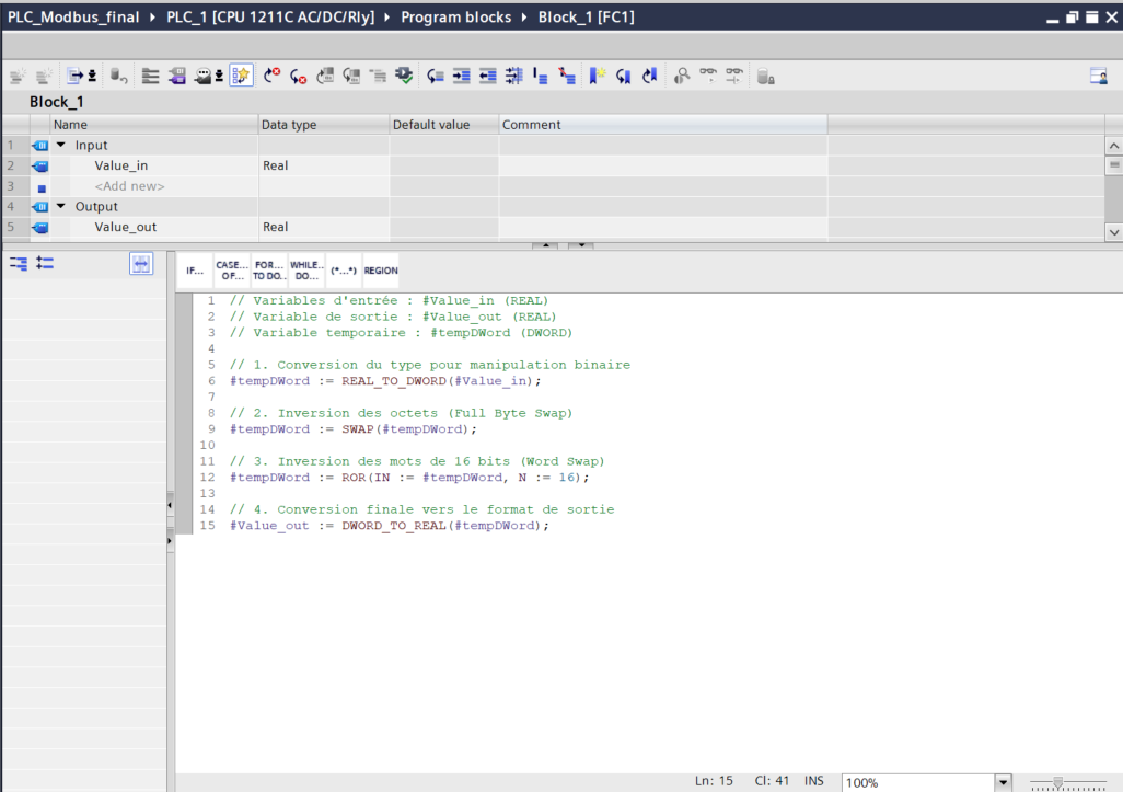
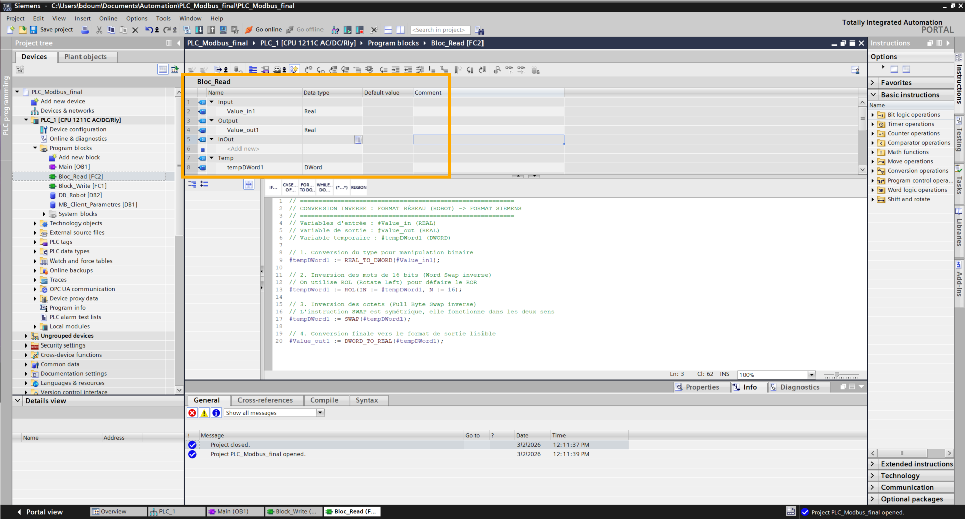
Copy the following code. This is used to reorganize the byte and word order of a floating point number (32 bits) to make it compatible between two different systems (such as a robot and a Siemens PLC).
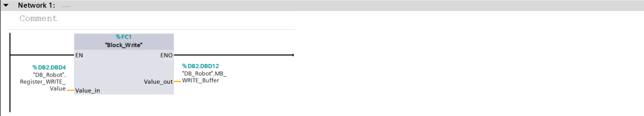
Then click on the Main [OB1]
Drag and drop the function block onto Network 1. Assign the input and output of this block as shown in the following image.
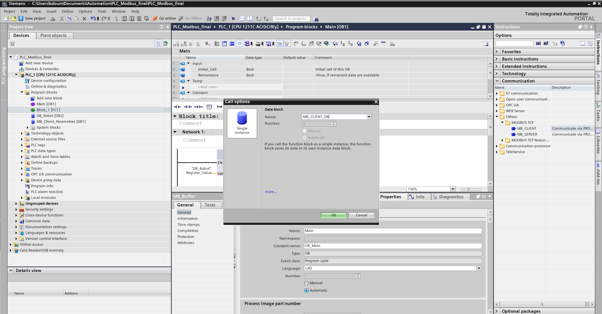
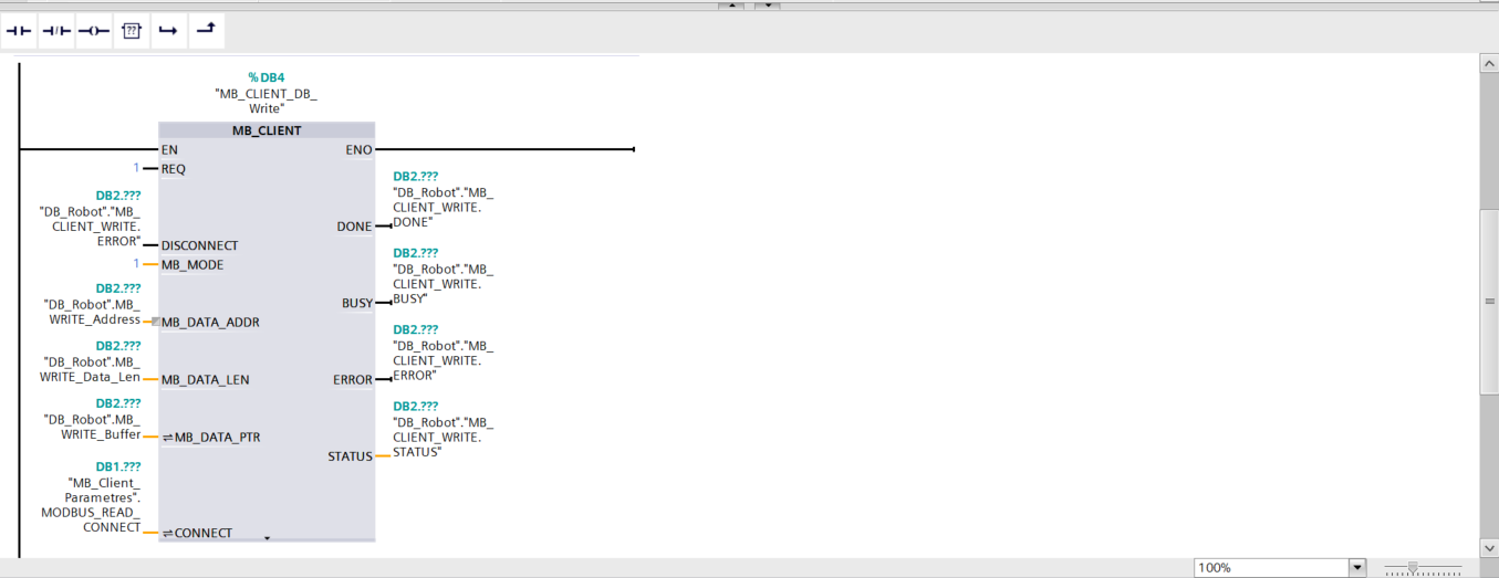
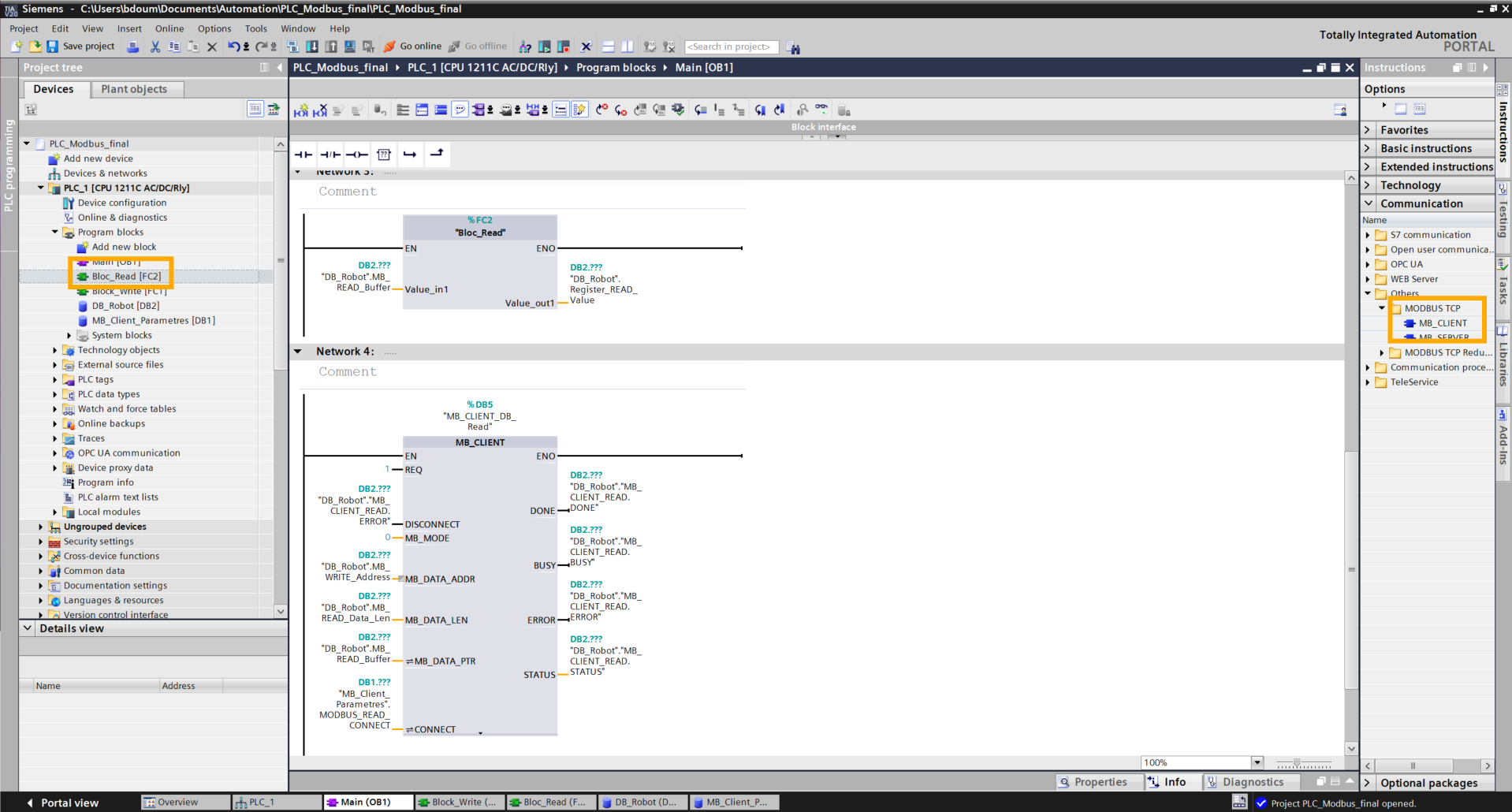
Drag and drop the MB_CLIENT module found in Instructions → Communication → Others → MODBUS TCP → MB_CLIENT onto Network 2.
Fill in the inputs and outputs as shown in the following image:
Compile each block finishing with the Main [OB1].
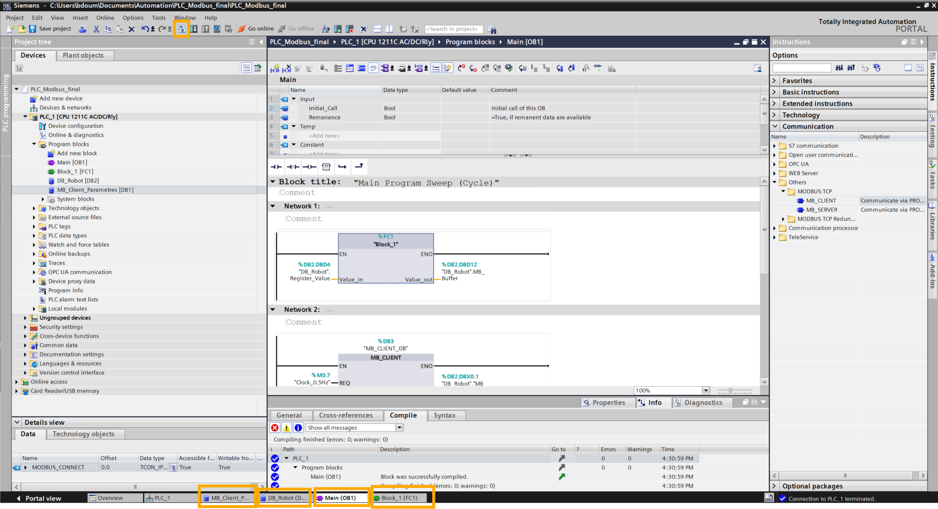
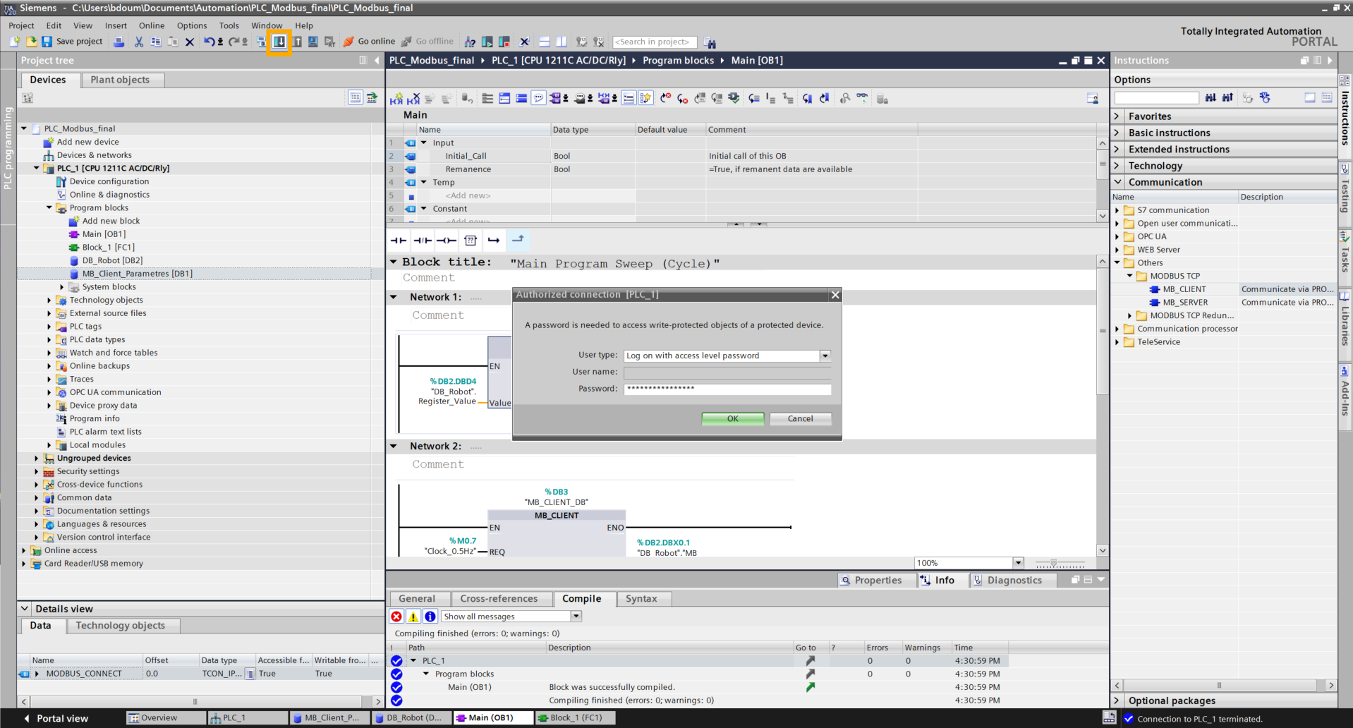
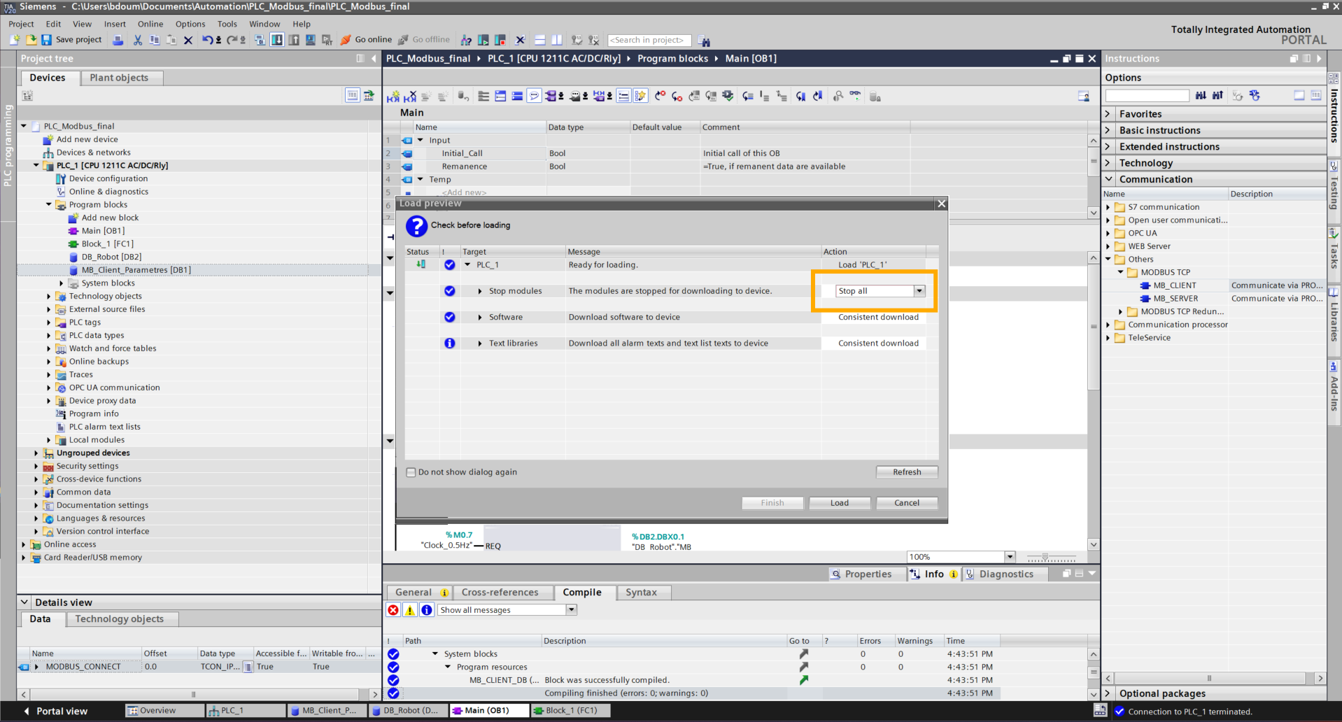
Then click on the Download to device icon and enter the previously configured password.
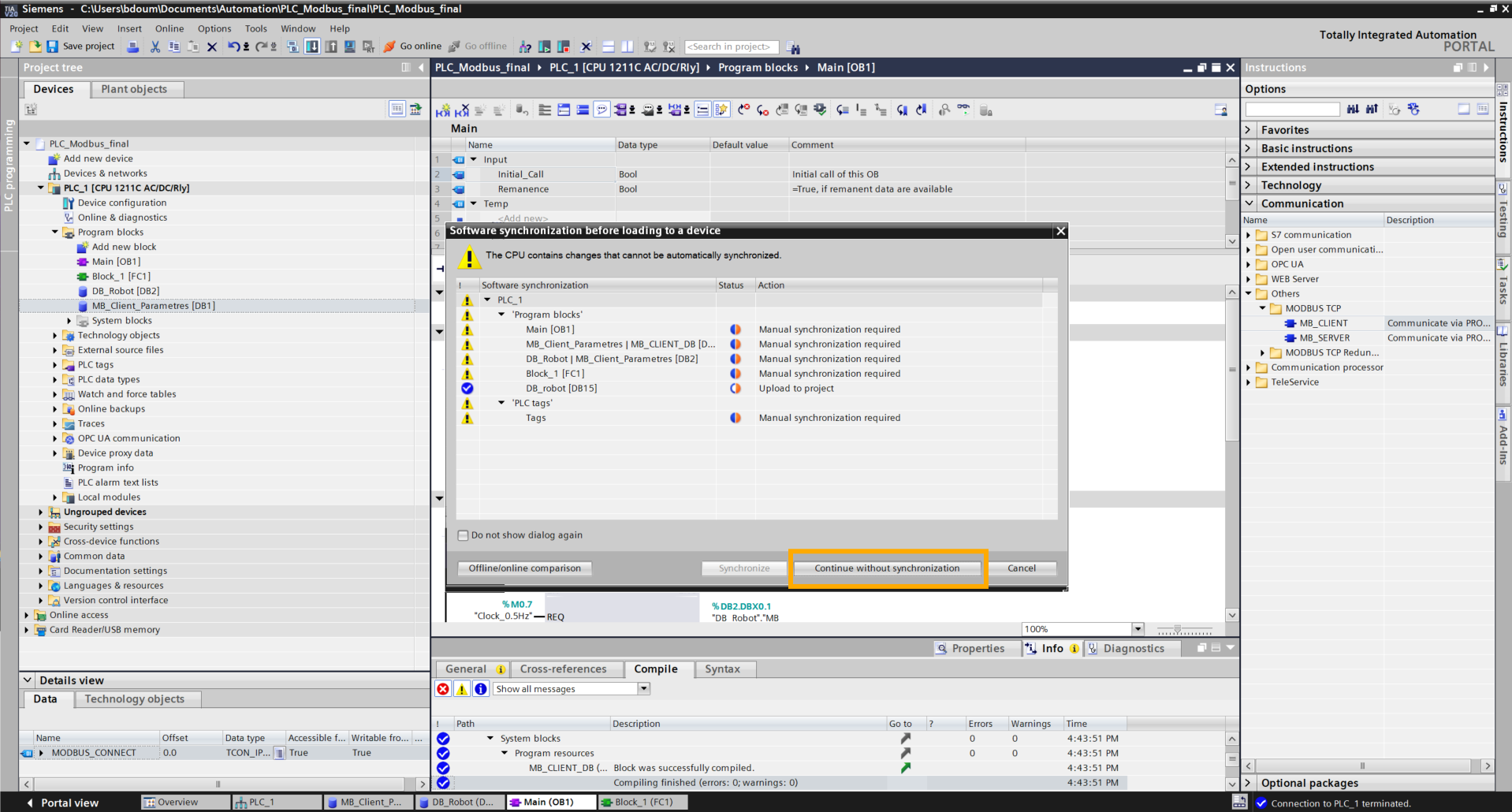
Click Continue without synchronisation.
Click on Load checking that Stop all is selected.
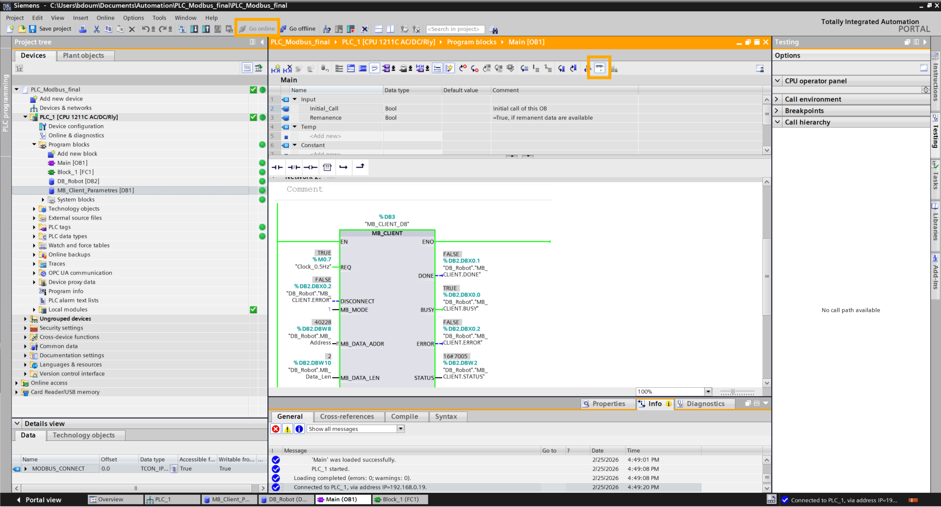
Click on Go online and activate dynamic monitoring.
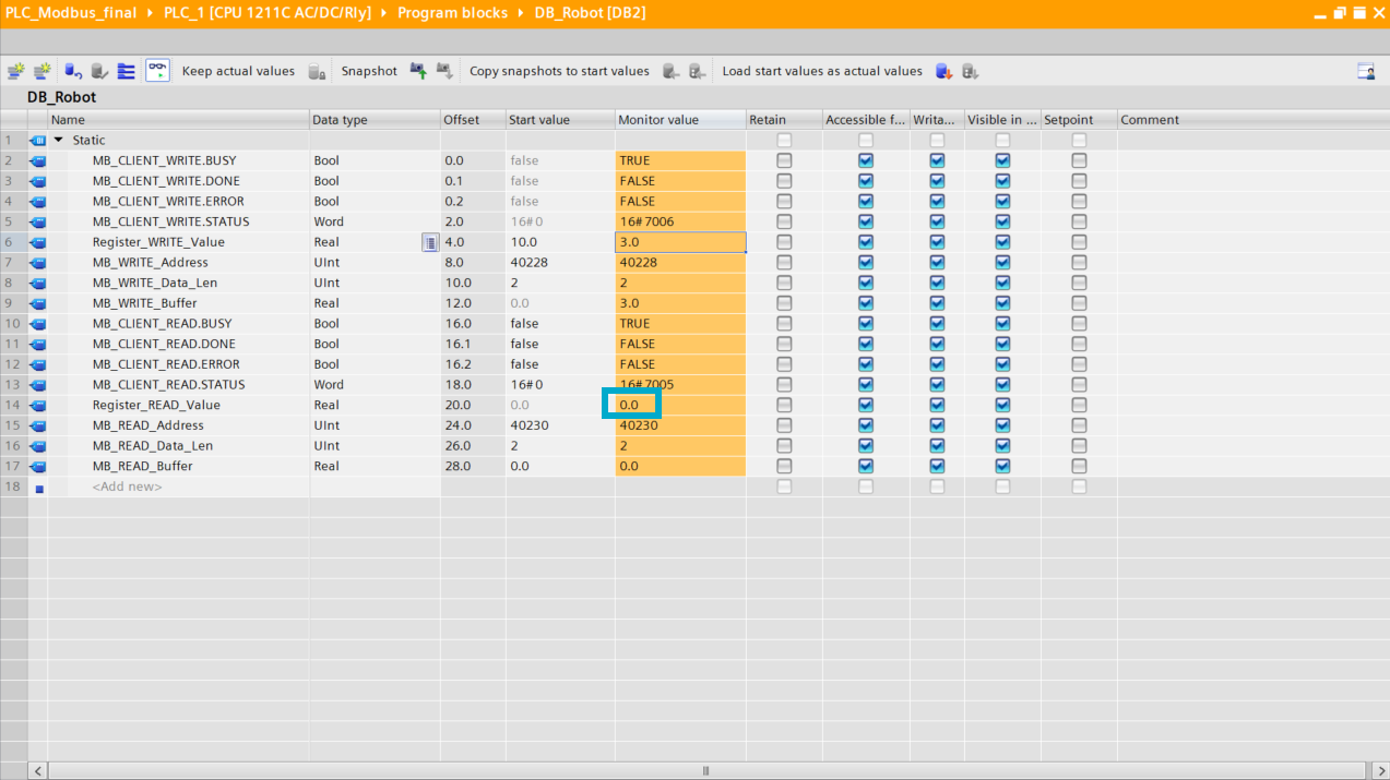
Go to the DB_Robot database window, activate dynamic monitoring and double-click on the value of the Register_value variable in the MONITOR_VALUE column. With this, you can define the value that will be written to the register and activate commands according to its value. Click OK.
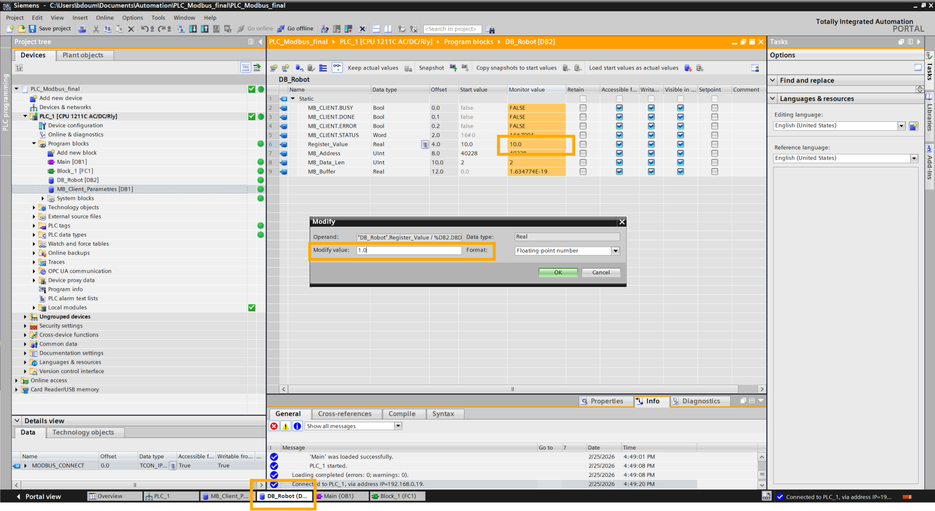
Having reached this step, the PLC can send commands (floating point values) to the robot so that it executes actions predefined in the code stored in the robot.
It is also possible to send data from the robot to the PLC to notify of a command status. We will see a simple example.
Create a new function. Choose a name.
Paste the code without forgetting to define the variables above. This code performs the inverse conversion done in the previous code.
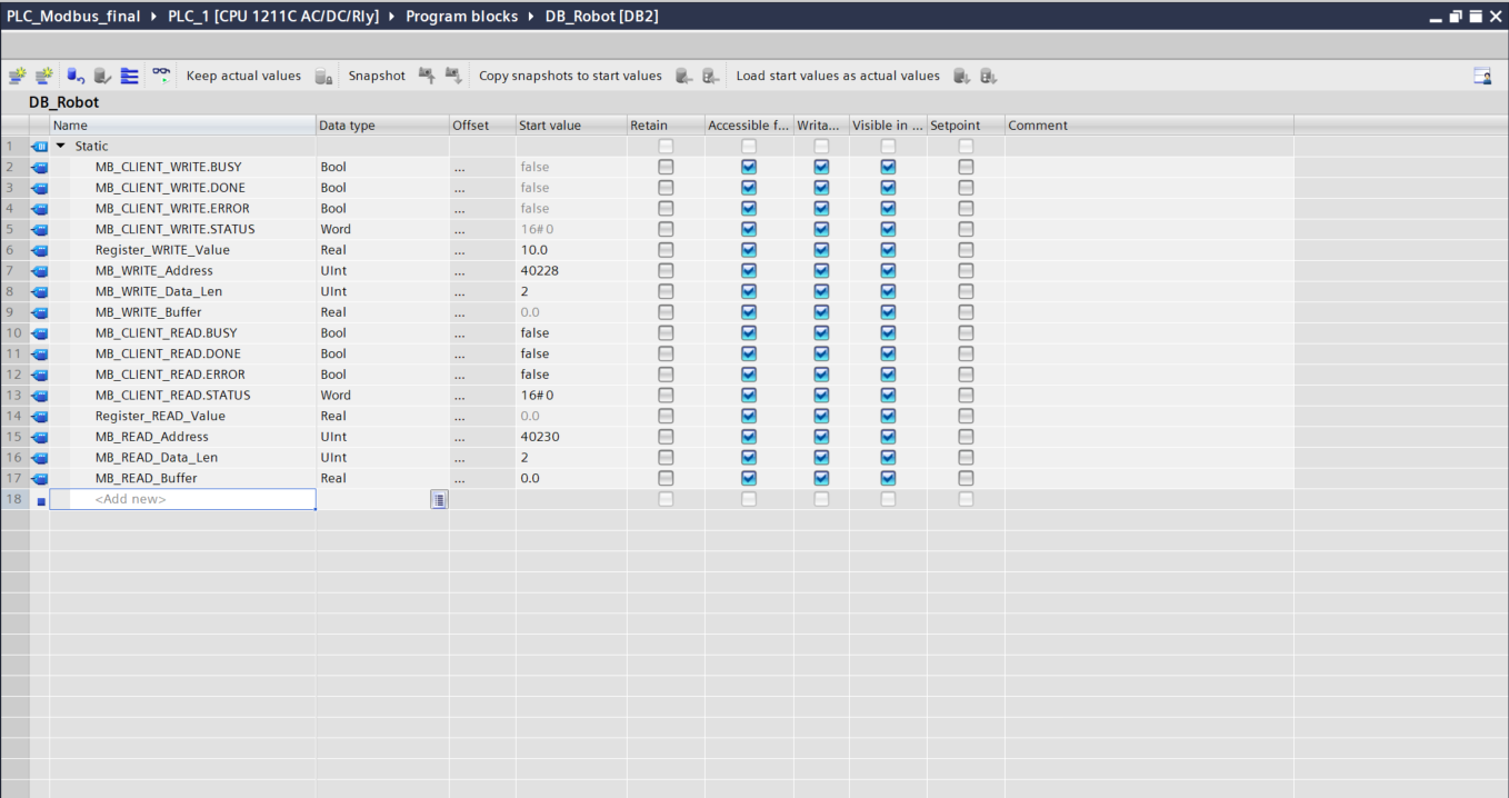
Go to DB_Robot and add the following variables:
-
MB_CLIENT_READ.BUSY (Bool)
- MB_CLIENT_READ.DONE (Bool)
- MB_CLIENT_READ.ERROR (Bool)
- MB_CLIENT_READ.STATUS (Word)
-
Register_READ_Value (Real): value sent by the robot.
-
MB_READ_Address (UInt): to dynamically change the value register. To choose the address, refer to the Modbus documentation from Niryo.
-
MB_READ_Data_Len (UInt): to change the size of the data received.
-
MB_READ_Buffer (Real): variable containing the value.
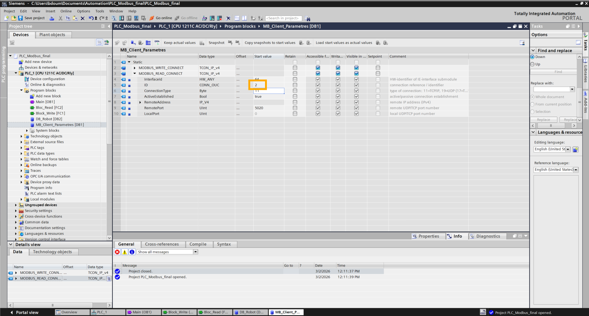
Go to MB_Client_Parametres and duplicate the block then modify the ID value (for example: 2).
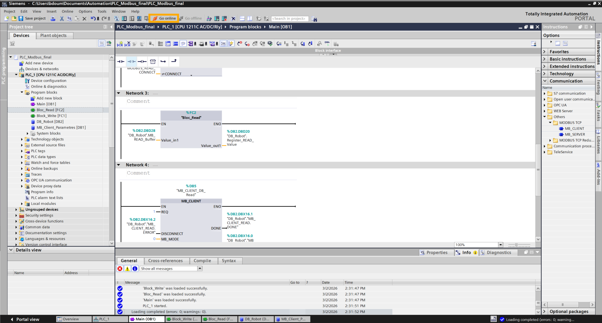
Go to Main and drag and drop the read block and an MB_Client block and fill in the inputs and outputs as shown in the following image:
Compile all the blocks and click on Download to device

Then click on Load.
On an IDE (Visual Studio for example), run this code on the robot forgetting not to make all the necessary modifications (IP address, workspace name, predefined actions).
The code is downloadable here.
Note that for Modbus, only the program with PyNiryo works.
Before moving on, here is a short explanation of this code.
1. Addressing and Key Registers
The dialogue relies on two specific memory areas:
- REG_COMMAND (227): the "dashboard" where the PLC writes its orders (1.0, 2.0, etc.).
- REG_STATUS (229): the "mirror" where the robot writes its state (action in progress or finished) so the PLC can read it.
2. The role of Decoding/Encoding
Since the PLC and the robot do not use the same byte order, the script uses two vital functions:
-
decode(): receives the "out of order" registers sent by the PLC and reshapes them into a real number (ex: transforms PLC signals into 2.0).
-
encode() : prepares the robot's status data (ex: 1.0 for "finished") in the inverse format so the PLC can read them correctly without error.
3. Command and status logic
The program runs in a loop according to this cycle:
-
Reading: the robot monitors register 227. If a new value appears, it launches the corresponding action (Home, Vision, or Trajectory).
-
Status: as soon as it begins, it writes 0.0 in register 229 (Busy). Once the movement is finished, it writes 1.0 (Ready).
Click on Go online.
Go to the DB_Robot database.
Status tracking is performed via the Register_READ_Value register. When an action is triggered (modification of the write register), this value changes to 0.0, then flips to 1.0 once the operation is finished.