Control of the Niryo Ned2 robot via an Allen Bradley PLC and CCW (I/O Adapter)
Tutorial
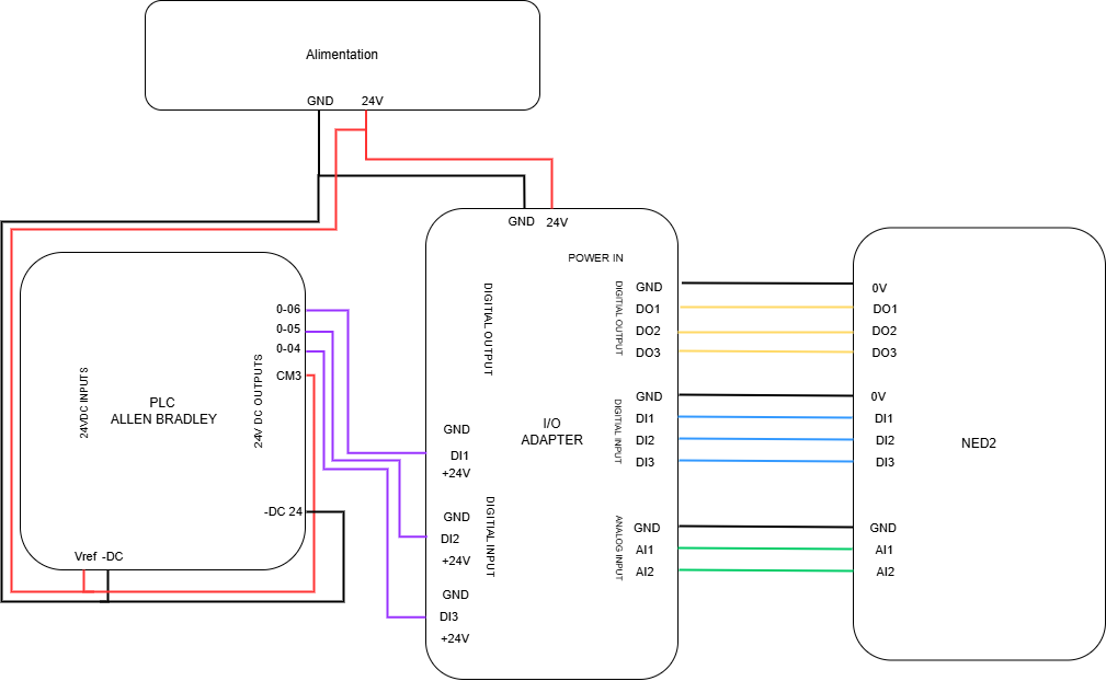
Electrical diagram:
In this first phase of the tutorial, we will see how to connect the I/O Adapter with the Allen Bradley PLC on one side and the Ned2 robot on the other. For this, a power supply that can provide 24 V is necessary (to power the I/O Adapter). We power the PLC outputs with its own 24V (cable connecting L+ to 1L). Here are the connections to follow:
Interface configuration in CCW (Connected Components WorkBench)
Before starting to configure the interface, we need to assign an IP address for the PLC.
To do that, download the BootP DHCP EtherNet/IP Commissioning Tool. The link can be found here.
Connect the PLC to the computer with an Ethernet cable and open the software.
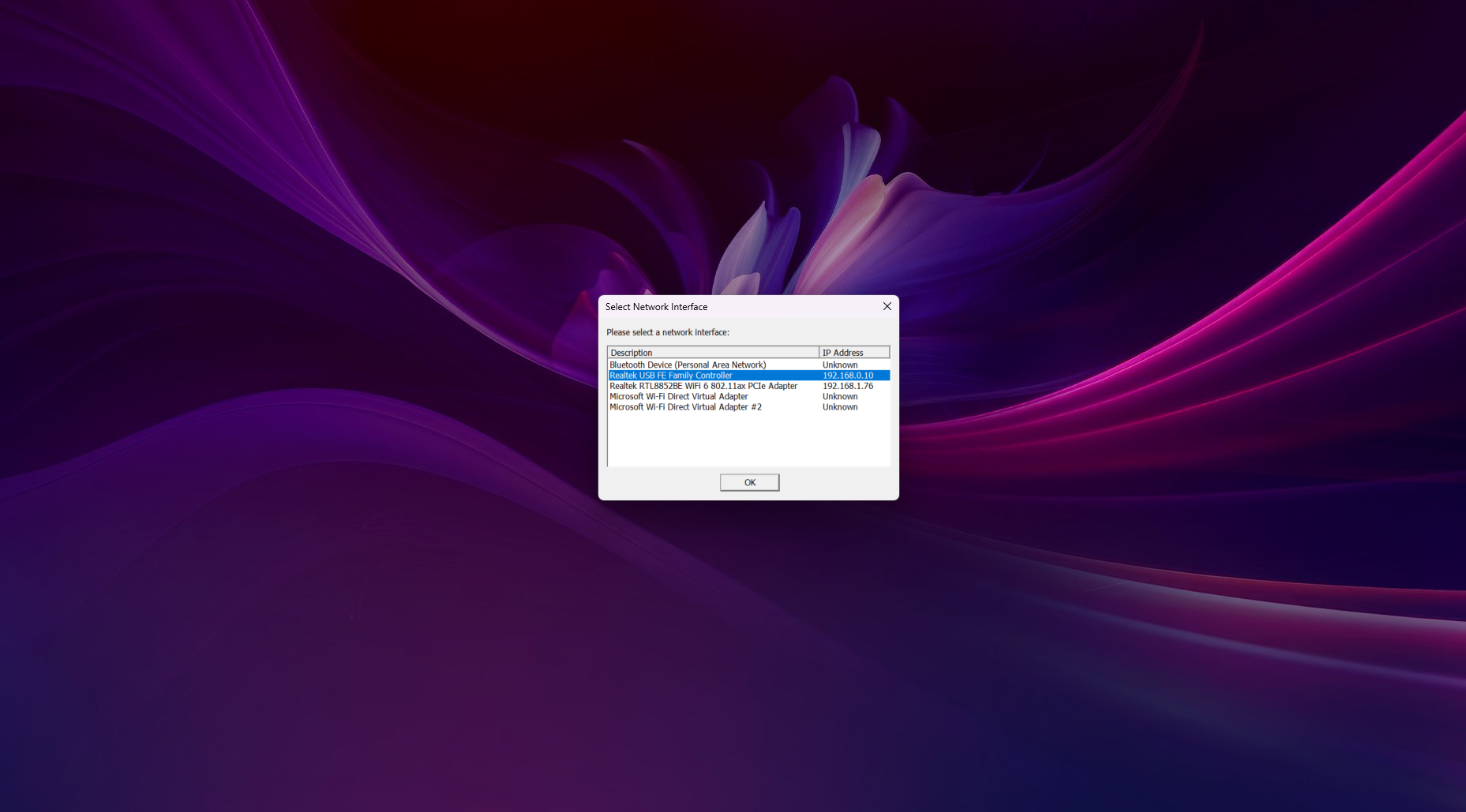
Select the network interface and click OK.
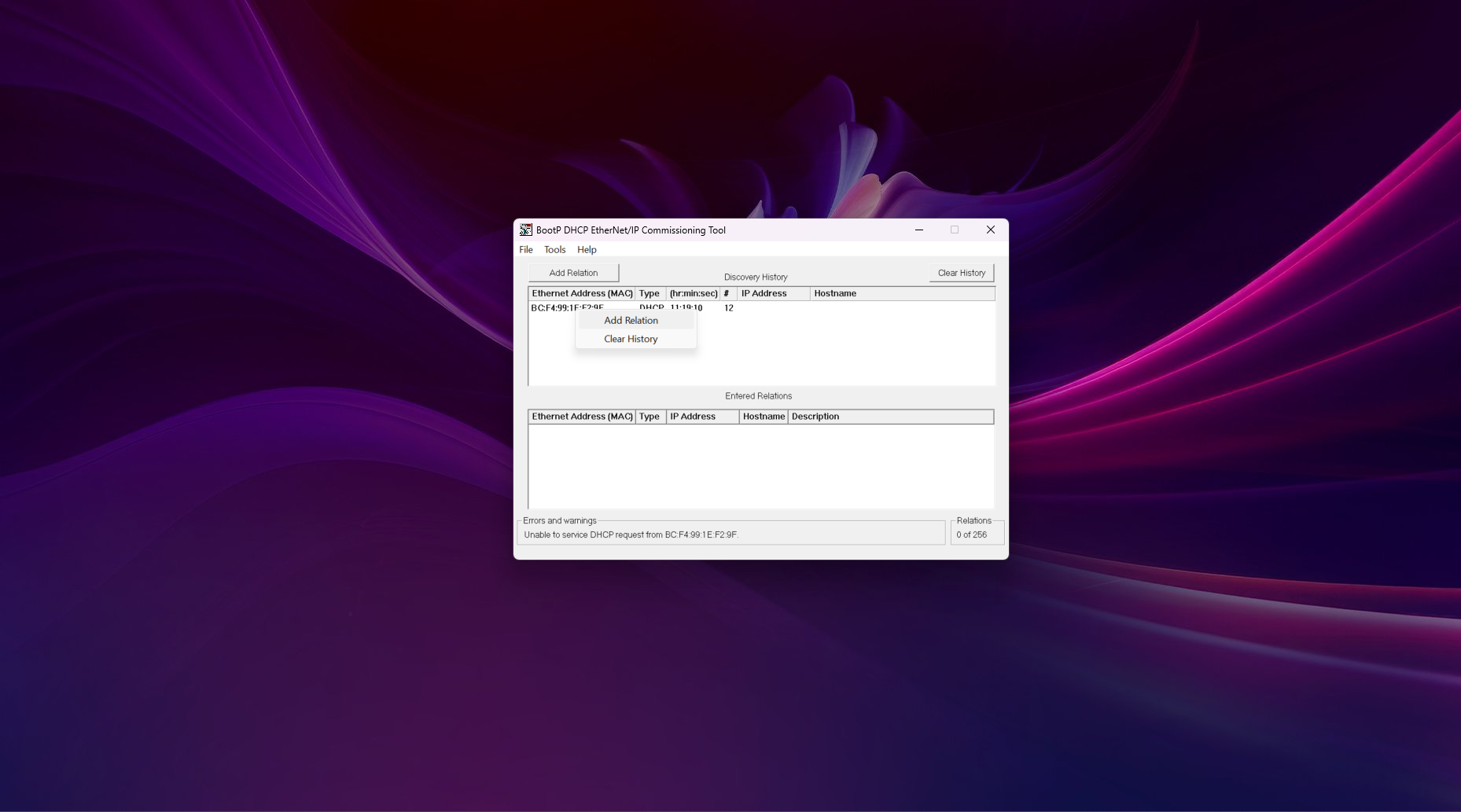
Wait a few times until the PLC is founded. As soon as this is the case, right-click on the Ethernet Address of the device, then click on Add Relation.
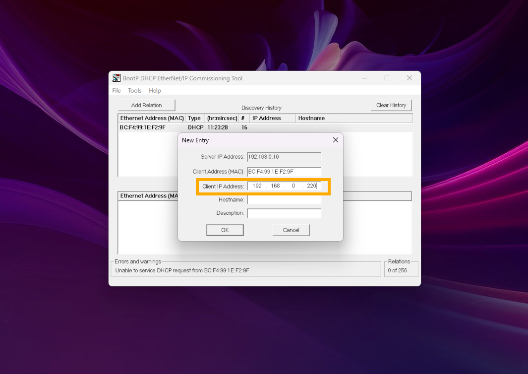
Choose an IP address on the same network as the PC. Then click OK.
Select the relation in the Entered Relations table and click on Disable BOOTP/DHCP.
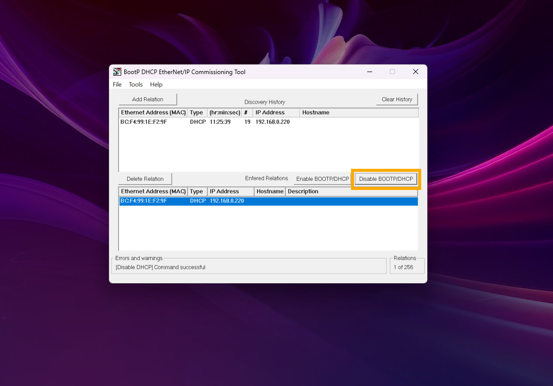
If the command is successful, quit the software.
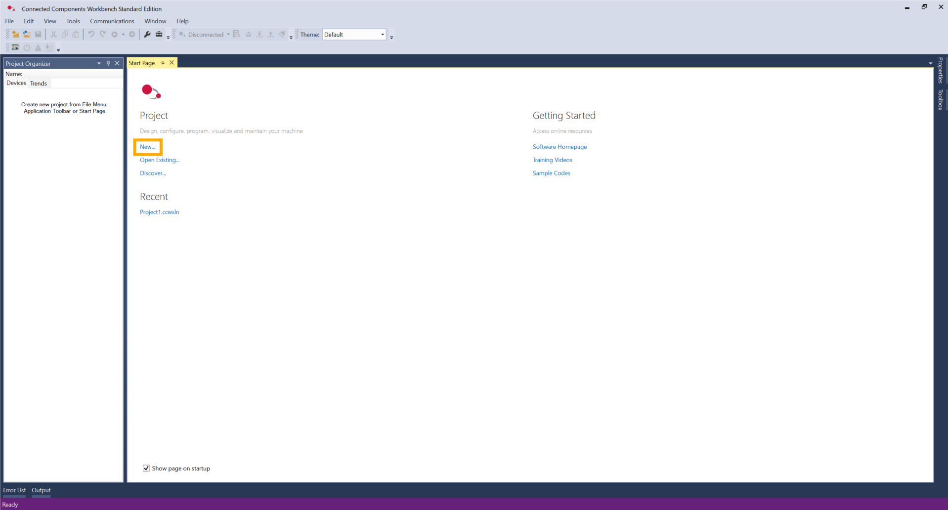
Then, open the CCW software. Create a new project.
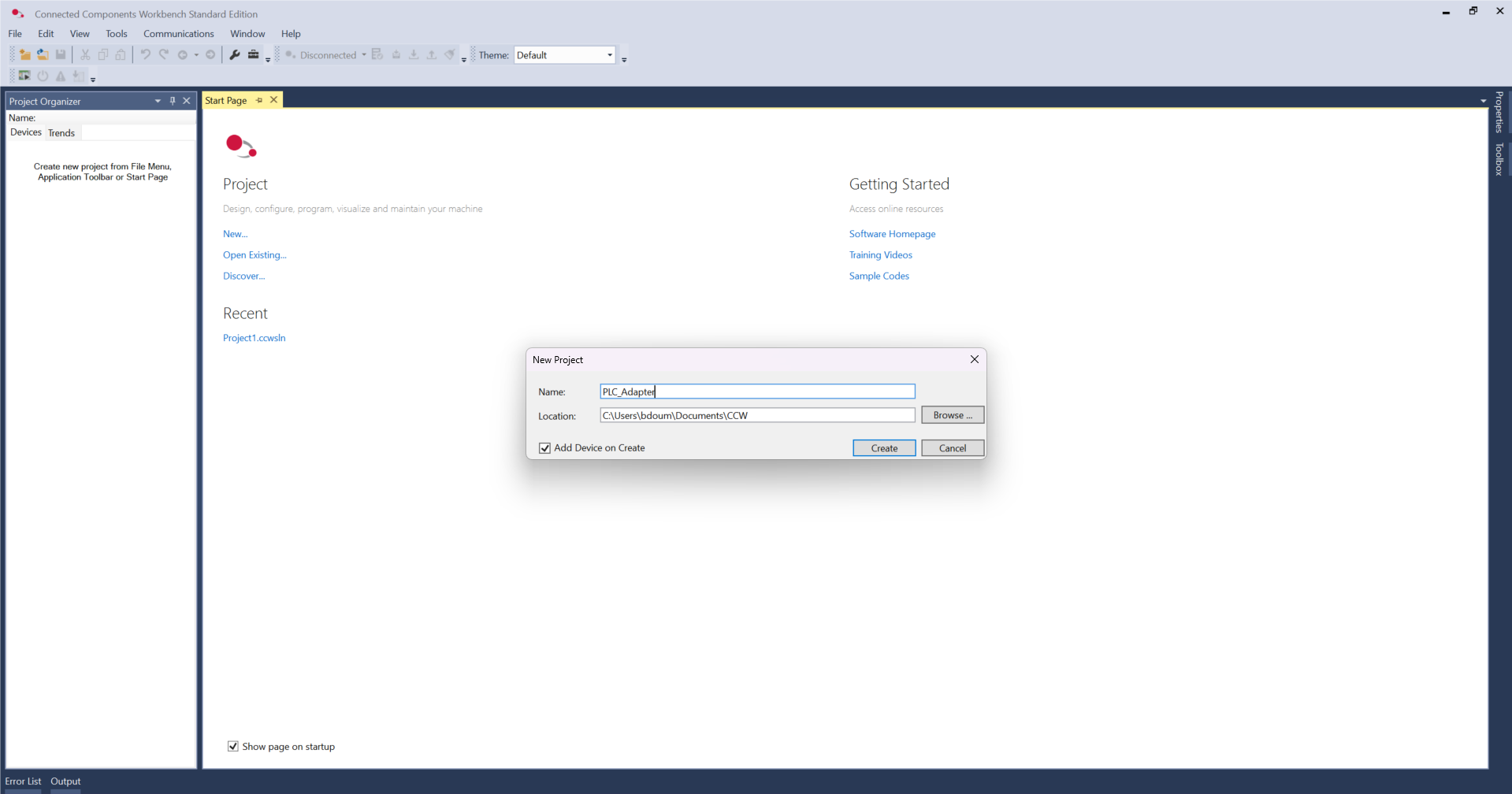
Define a name and click Create.
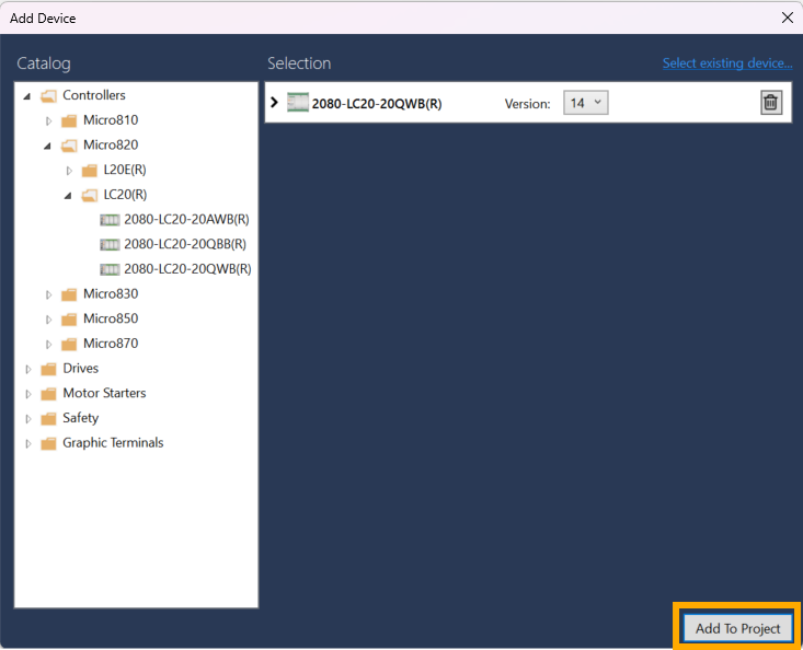
In the Controllers folder, select the reference of the PLC.
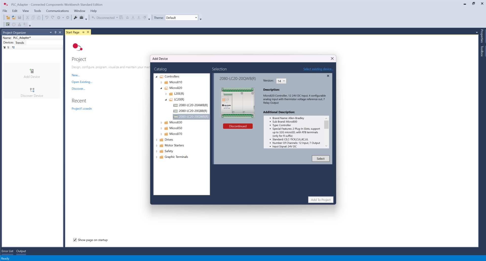
Click Select and Add To Project.
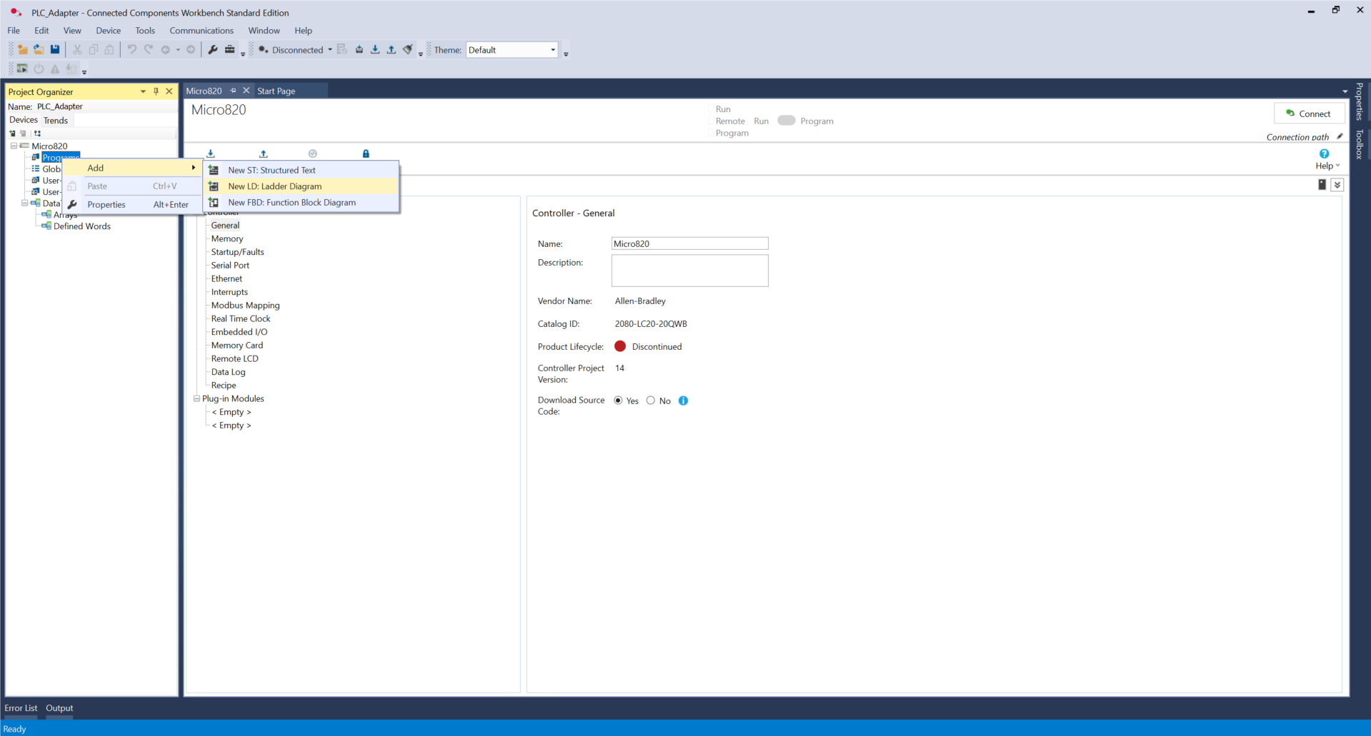
Then, right-click on Programs -> Add -> New LD: Ladder Diagram. Rename it Main.
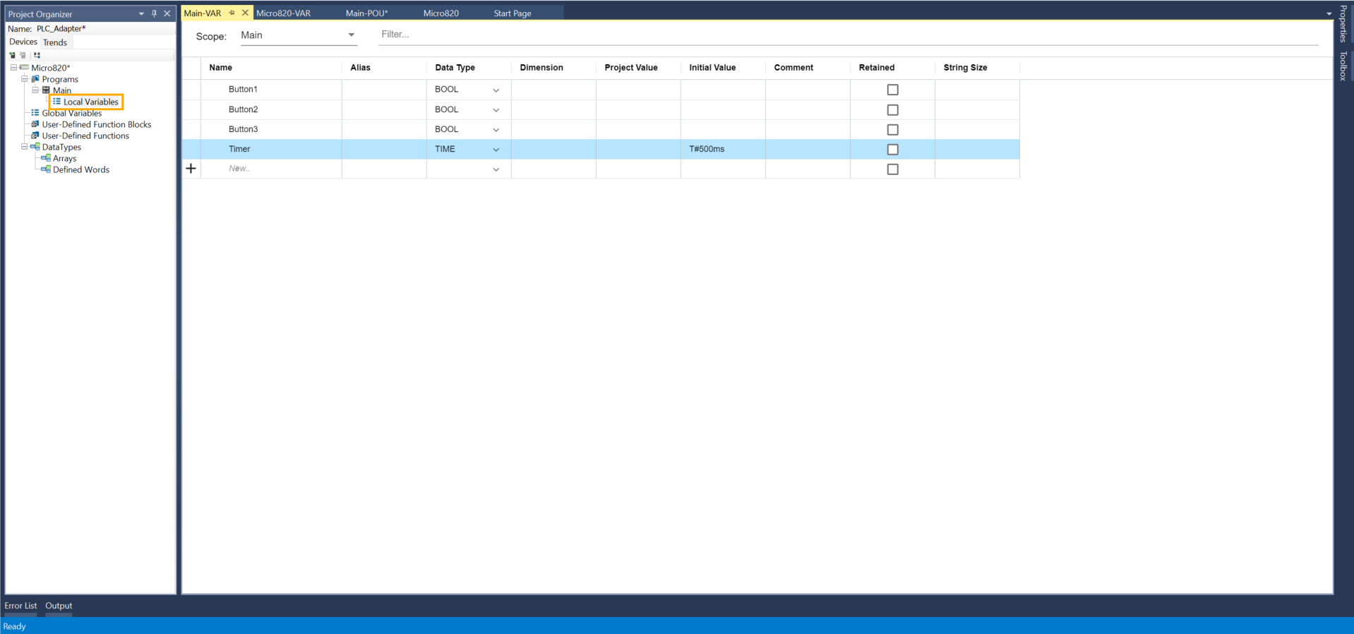
In this step, we will create three simulated buttons to send commands to the I/O adapter and, finally, to the robot. They will have the same behavior as physical push buttons.
For that, go to Local Variables and create three boolean variables: Button1, Button2, and Button3. Add another variable, Timer, with a TIME data type and an initial value of T#500ms. That will be the impulsion time of these buttons.
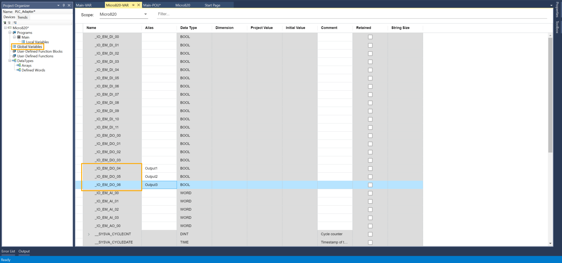
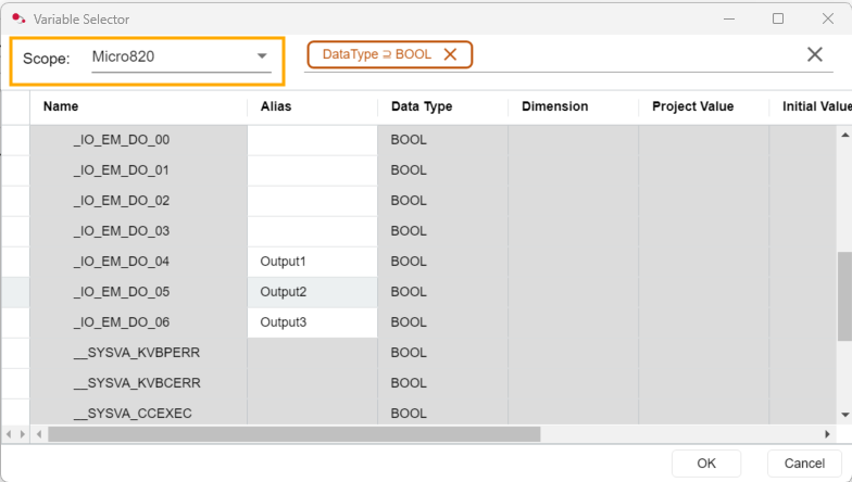
Then go to the Global Variables panel and choose three outputs in the table. In the Alias column, set these outputs with the following names: Output1, Output2, and Output3.
Go to Main.
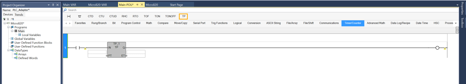
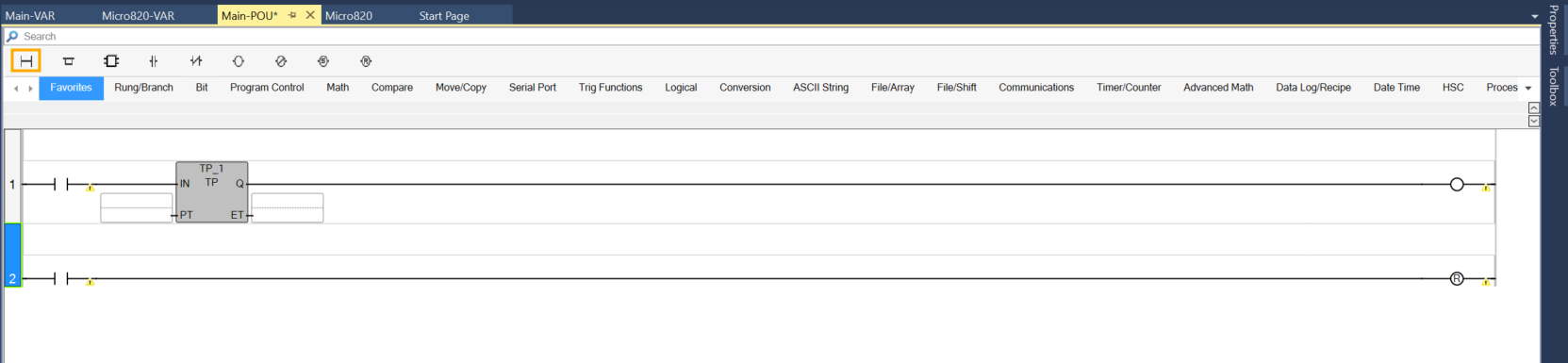
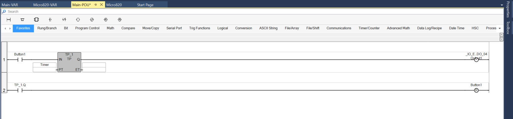
In the first Rung, add a Direct Contact, a TP timer block, and a Direct Coil.
Create a new Rung and add another Direct contact and Reset coil.
Double-click on the first Direct Contact, and in the Scope field, choose Main.
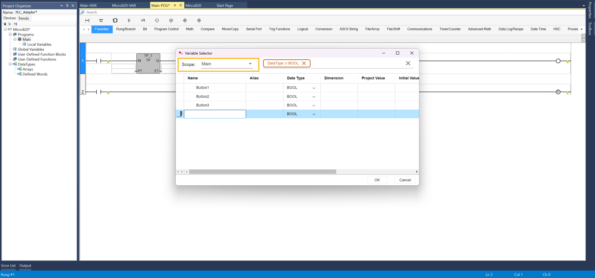
Then double-click on Button1 to assign this variable.
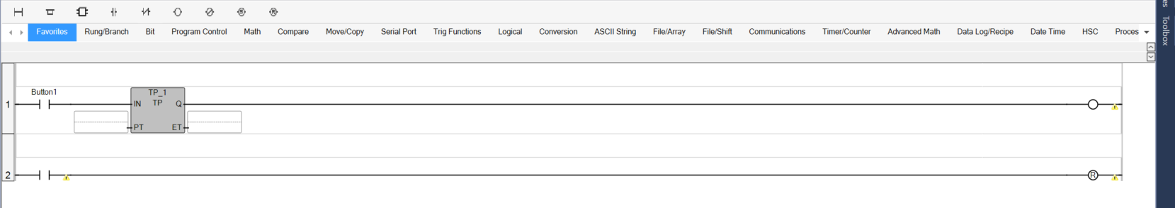
Make the same for all elements. For the ouput, choose in the Scope field, the PLC model option. In our case, it is the Micro820.
On the second Direct Contact, enter TP_1.Q. To explain the logic: when the Button1 Direct Contact is forced to 1, the timer output (Q) and the coil are set to 1 for a duration of 500 ms. The second contact then allows the Button1 Direct Contact to be reset, effectively simulating the release of the physical button.
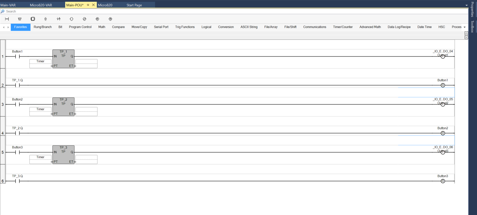
Duplicate the same logic for the second and third buttons.
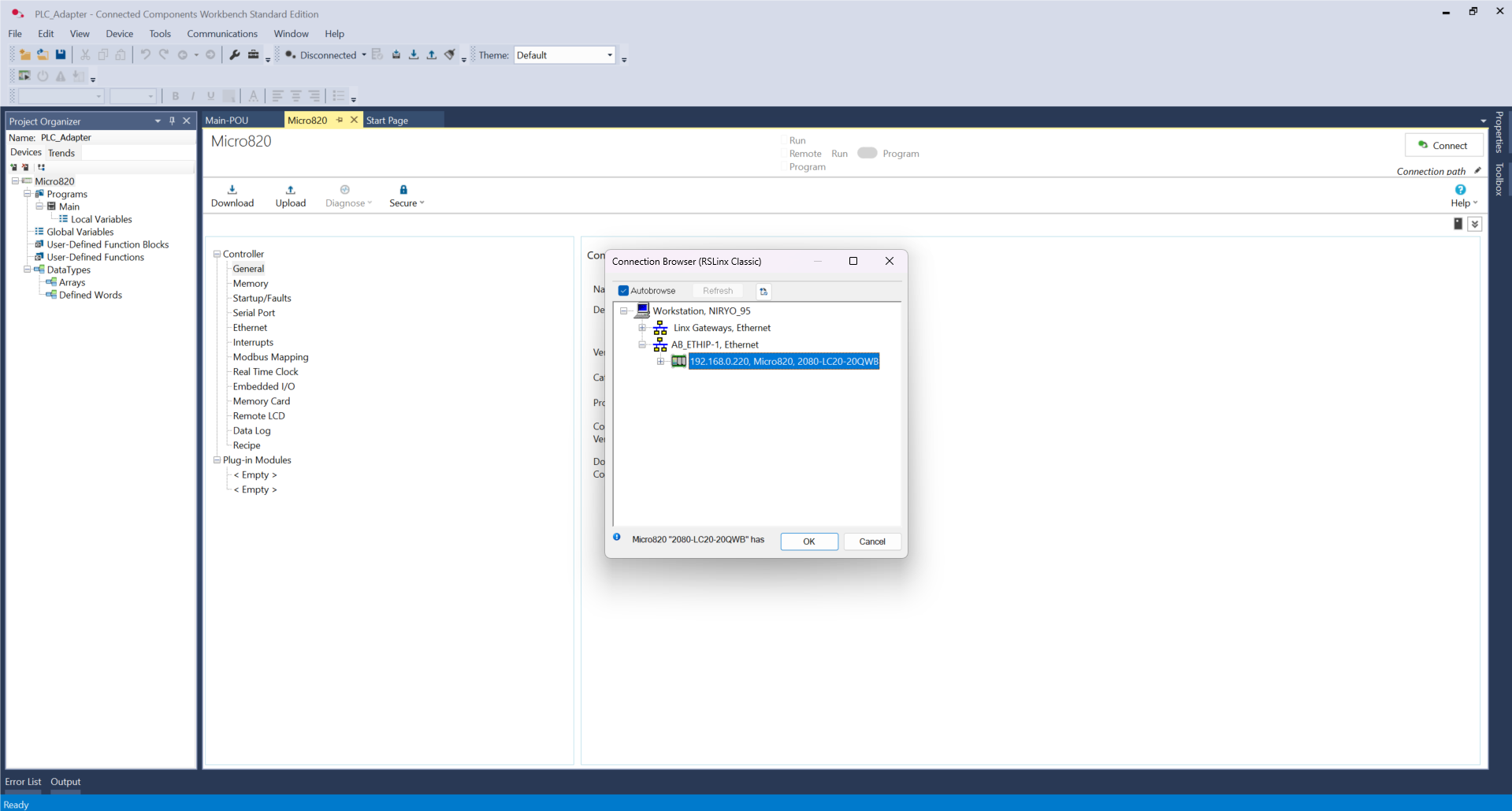
On the top page, click on Connect
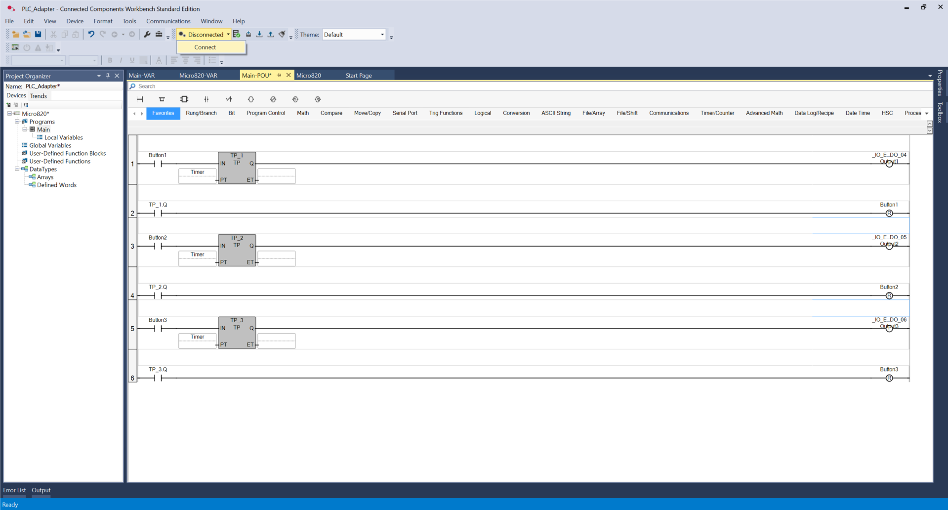
Select the PLC and click OK.
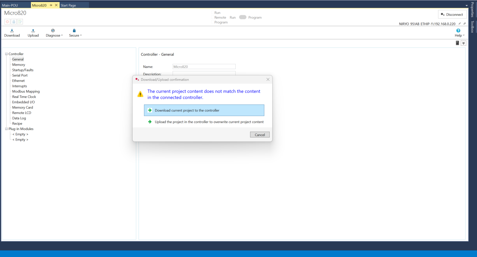
Click on Download current project to the controller.
Again, click on Download.
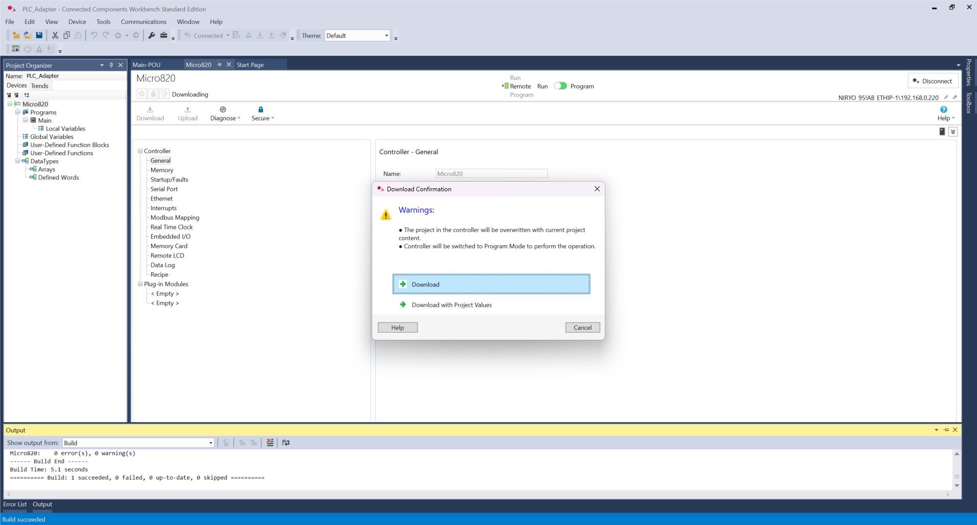
Click Yes.

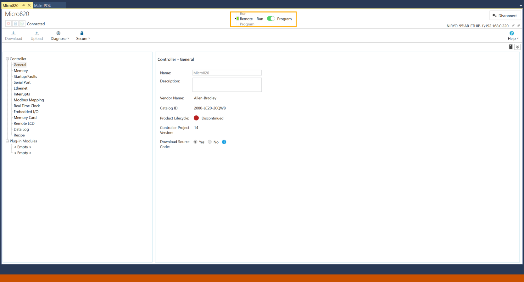
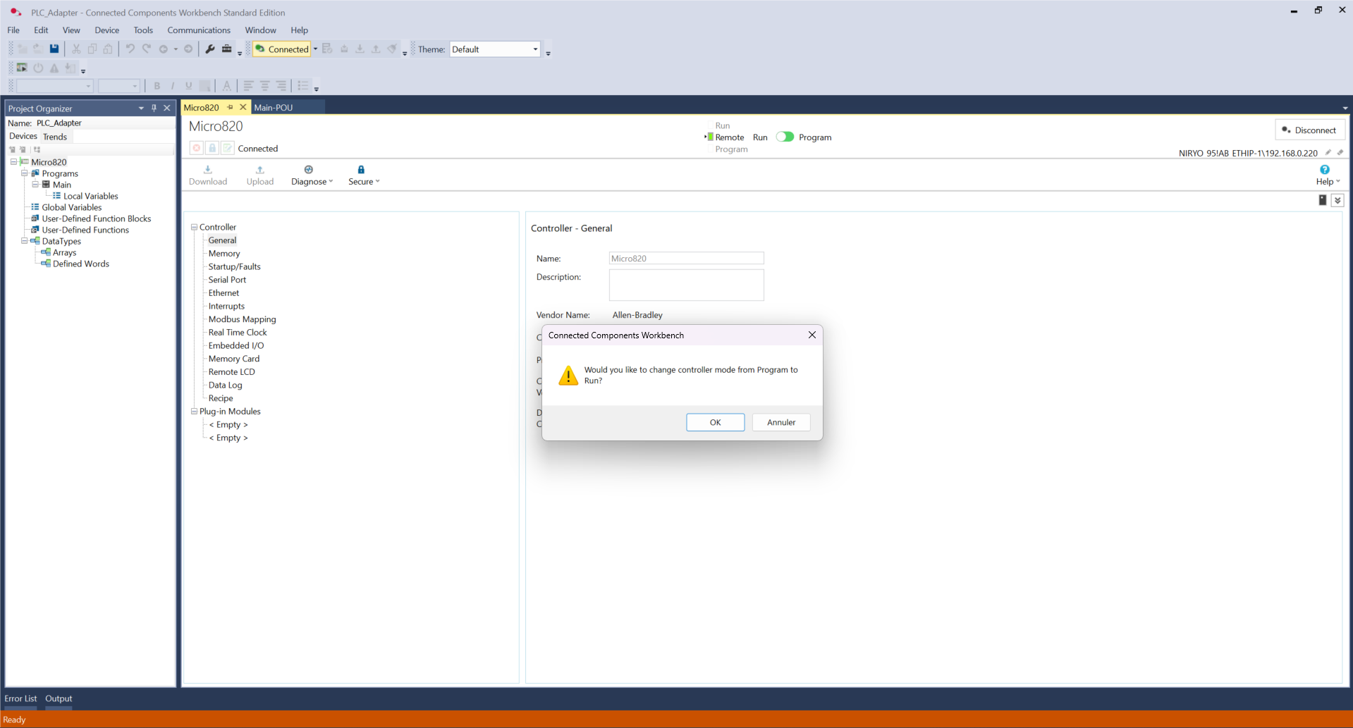
Click on the switch to toggle from Program to Run, and click OK.
Now our program is configured on the PLC side. In the next steps, we will see how we can use these commands to allow the robot to make some actions.
Robot-side programming
This script allows the robot to be controlled directly by electrical signals sent by the PLC to its ports DI1, DI2, and DI3. In an IDE (Visual Studio), copy the code found here.
Here are some explanations to better understand its role.
1. Hardware Interaction
This code queries the physical state of the robot pins :
-
Reading signals: the robot.digital_read() function continuously monitors if a voltage is present on the inputs.
-
PinState.HIGH: the robot detects if a button is pressed or if the controller sends an "All or nothing" signal (24 V transformed to 5 V).
2. Role of Physical Commands
The logic is simplified into three direct actions triggered by each input:
-
DI1 (Input 1): starts the auto calibration procedure to reset the motors.
-
DI2 (Input 2): orders an immediate move to the HOME position.
-
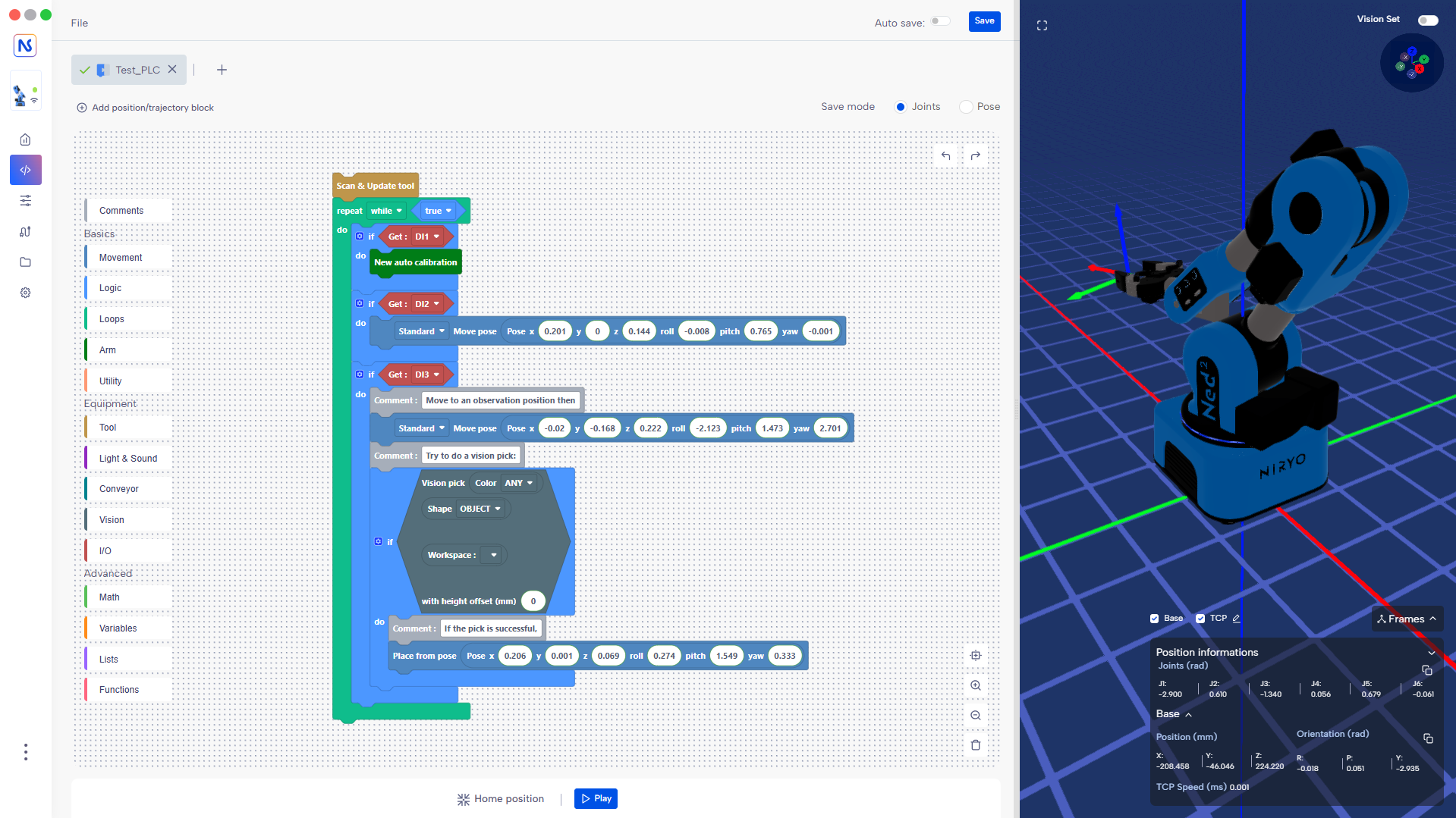
DI3 (Input 3): triggers the Vision Pick & Place cycle.
3. Logic and Stability
-
Control loop: the program scans the inputs every 0.5 seconds (robot.wait(0.5)) to avoid saturating the processor while remaining responsive.
-
Priority: the if/elif structure ensures that only one action is processed at a time, thus preventing the robot from attempting to perform two contradictory movements simultaneously.
There is a Blockly version, which can be found here.
Tests
In CCW Software, go to the Main-POU and double-click on the Button1 contact.
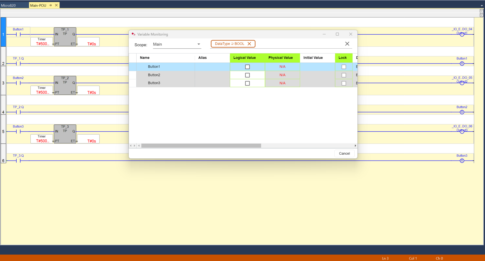
To activate a button, check the box in the Logical Value column. Now we can control the robot with this PLC.