Control of the Niryo Ned2 robot via a Allen Bradley PLC and CCW (Modbus)
Interface configuration in CCW (Connected Components WorkBench)
Before starting to configure the interface, we need to assign an IP address for the PLC.
To do that, download the BootP DHCP EtherNet/IP Commissioning Tool. The link can be found here.
Connect the PLC to the computer with an Ethernet cable and open the software.
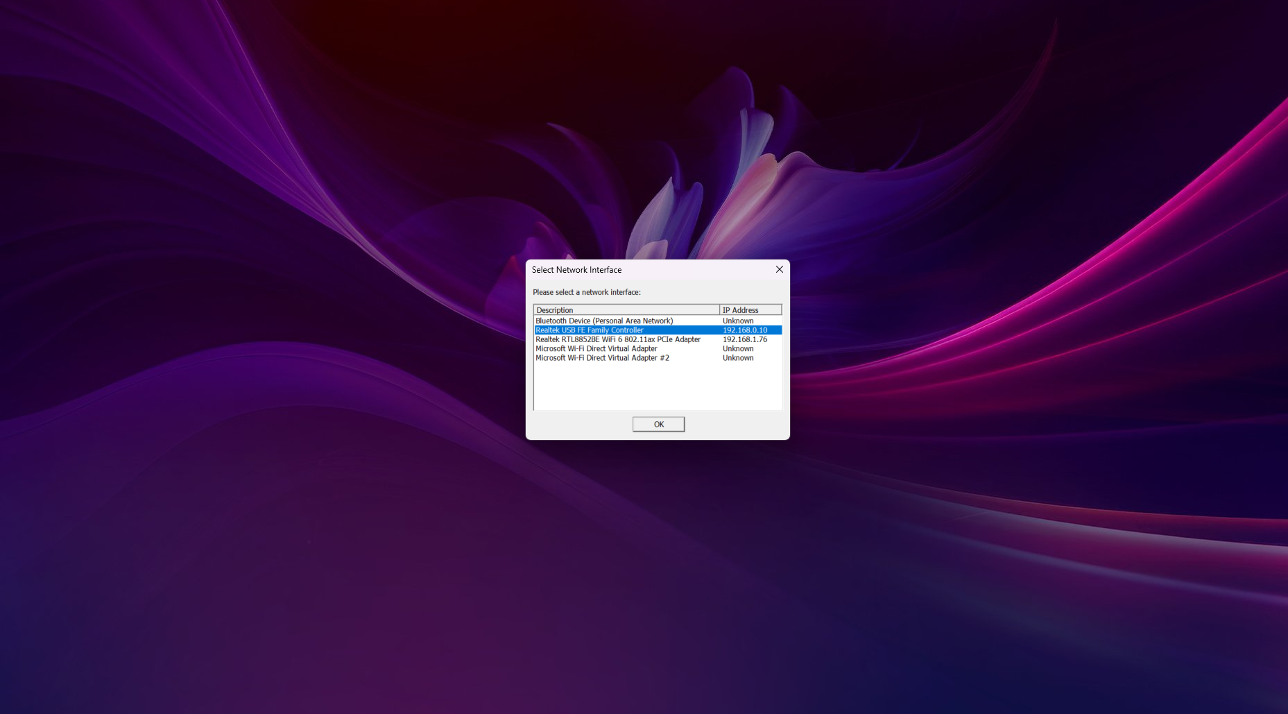
Select the network interface and click OK.
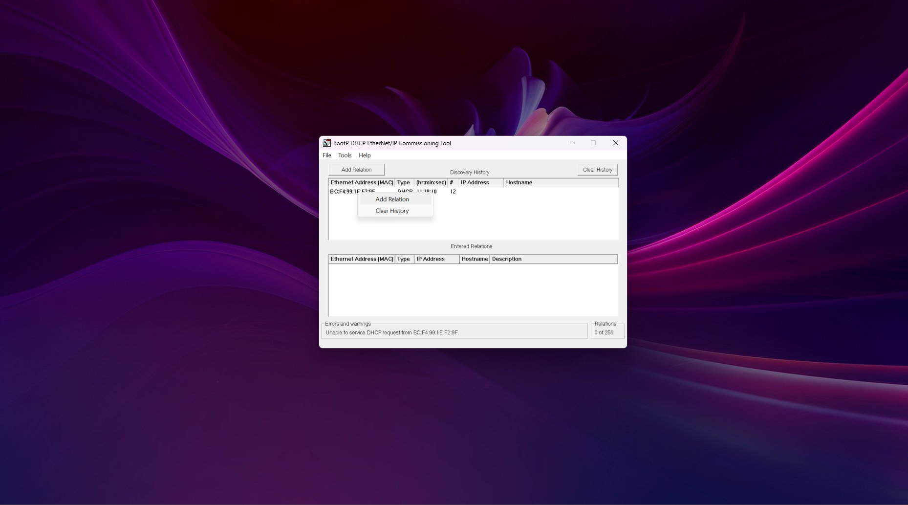
Wait a few times until the PLC is founded. As soon as this is the case, right-click on the Ethernet Address of the device, then click on Add Relation.
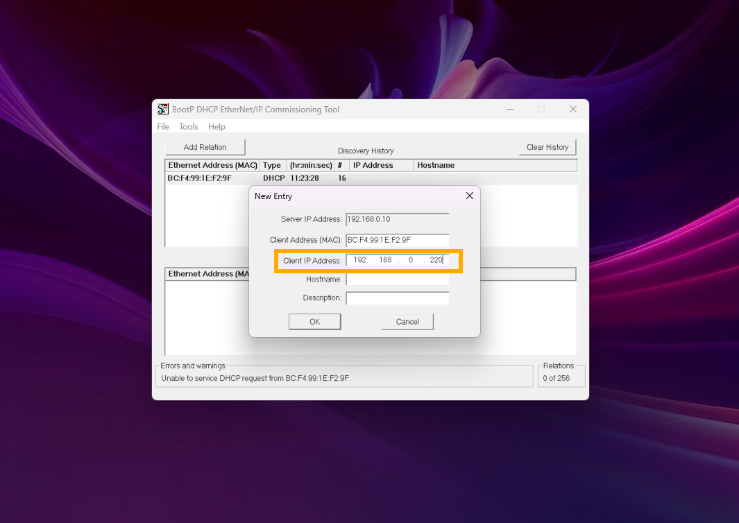
Choose an IP address on the same network as the PC. Then click OK.
Select the relation in the Entered Relations table and click on Disable BOOTP/DHCP.
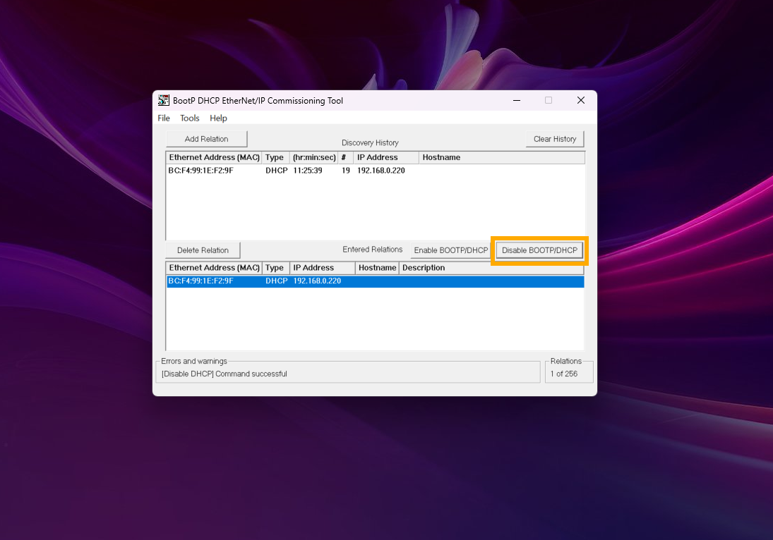
If the command is successful, quit the software.
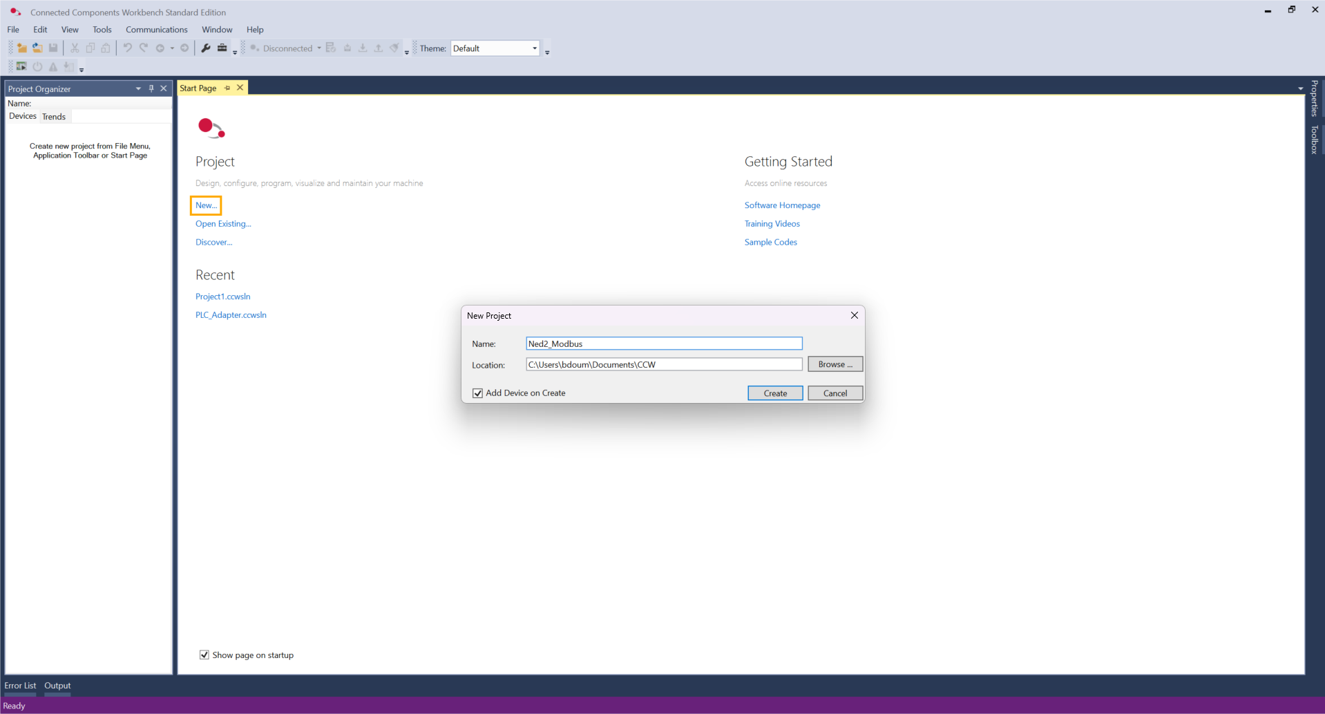
Then, open the CCW software. Create a new project, define a name, and click Create.
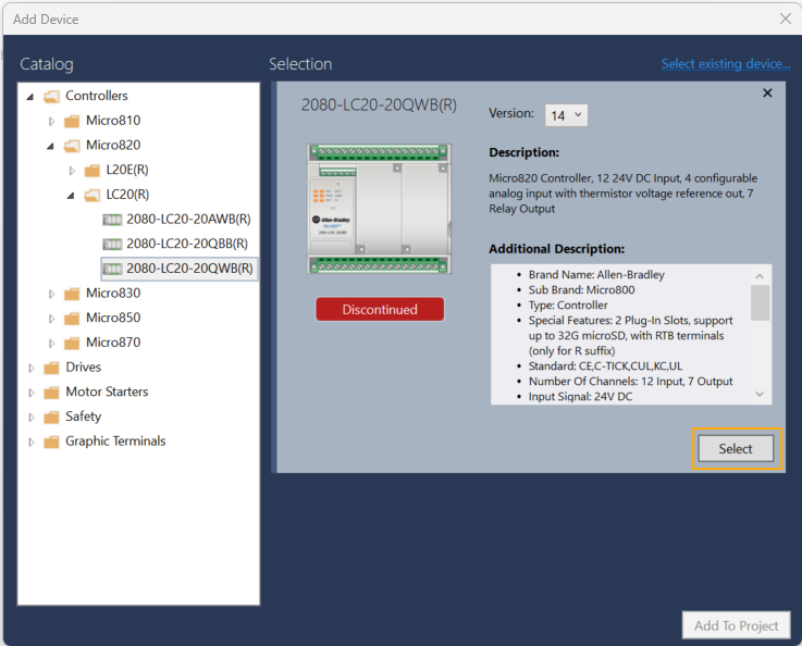
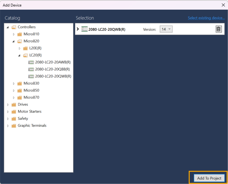
In the Controllers folder, select the reference of the PLC.
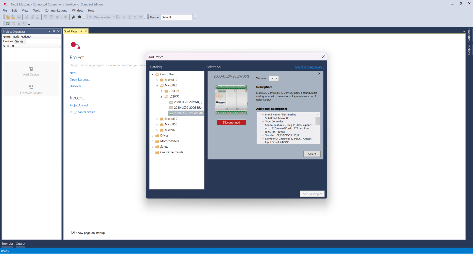
Click Select and Add To Project.
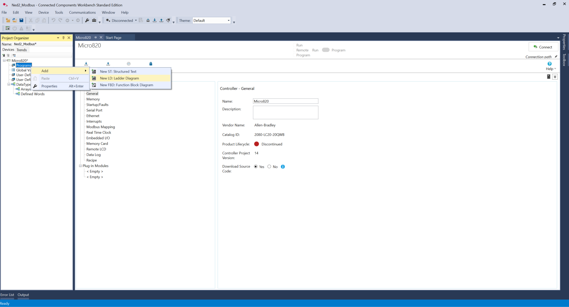
Then, right-click on Programs -> Add -> New LD: Ladder Diagram. Rename it Main.
During the next steps, we are focusing on reading values through the Ned2 robot's registers.
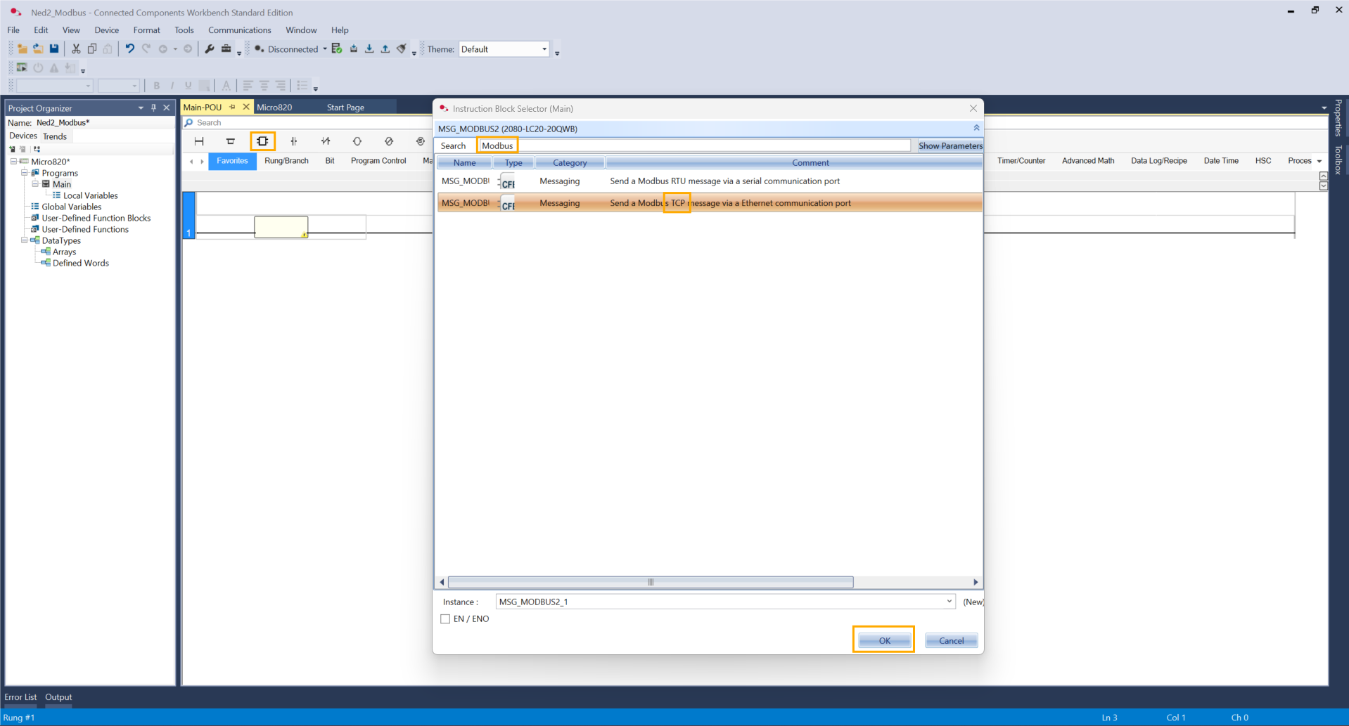
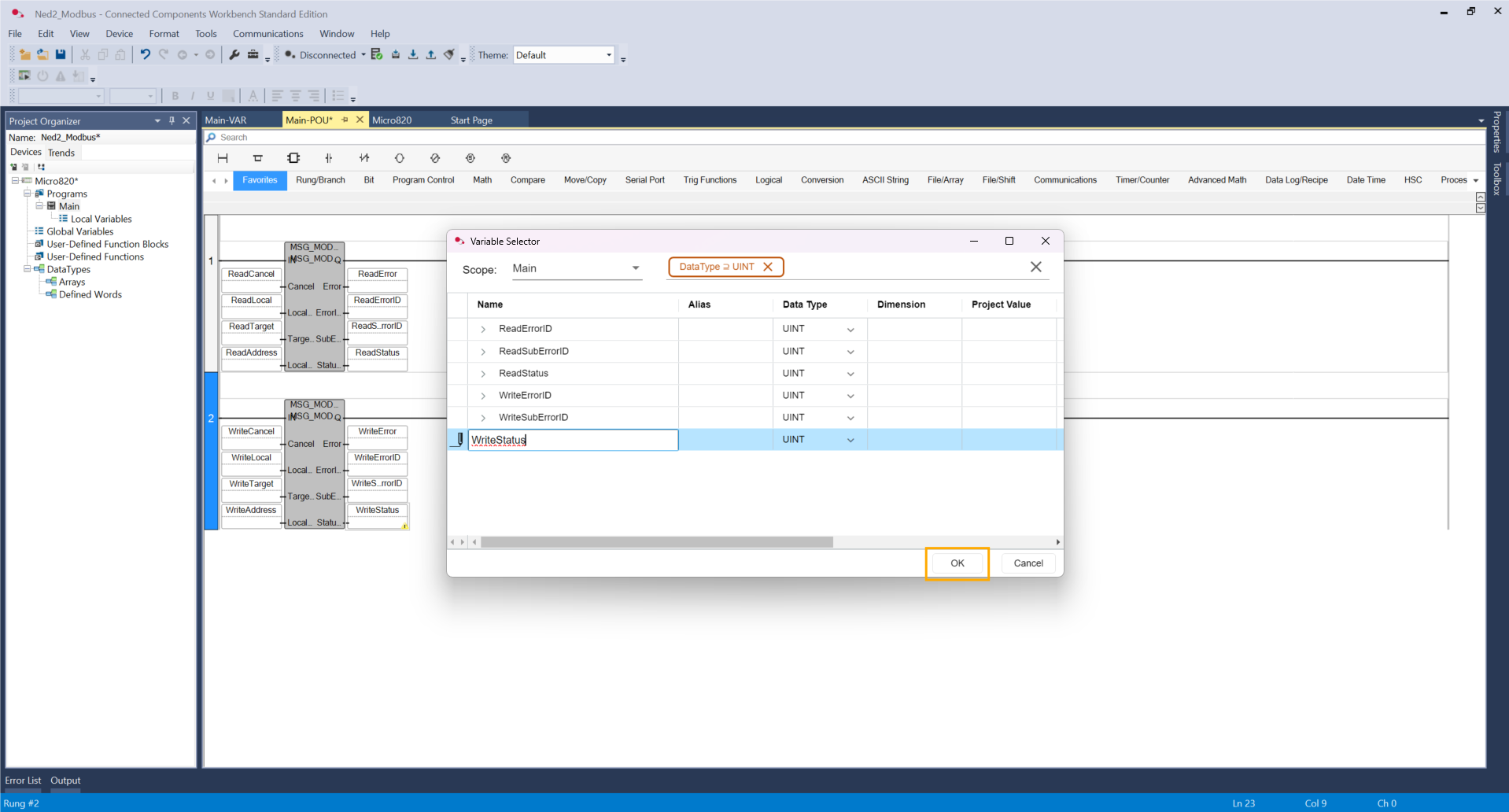
For that, on the first rung, add an instruction block, search Modbus, and select the TCP option. Click OK.
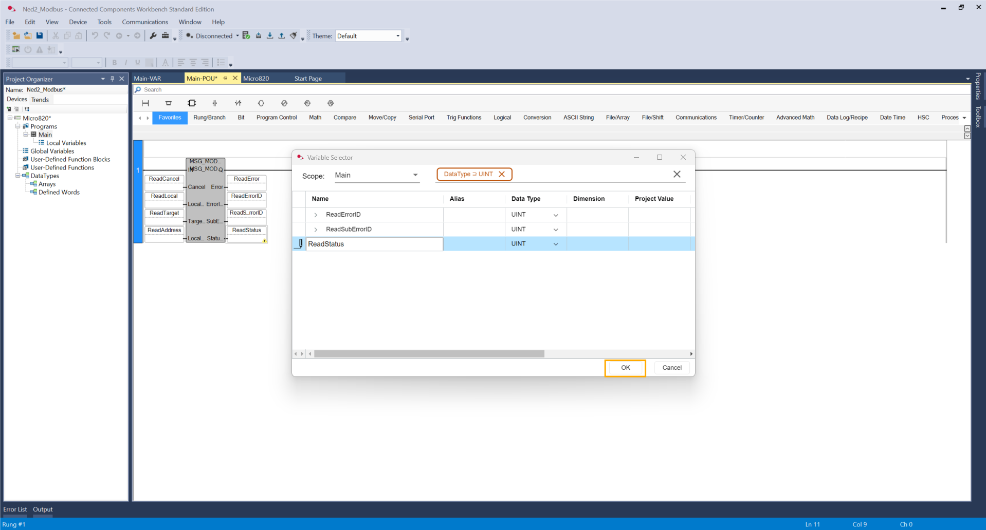
Add variables on the pins, and please keep in mind for each variable to double-click on the box and click OK.
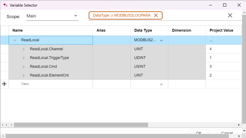
Double-click on the ReadLocal variable. Let's configure with these parameters.
-
Channel: Specifies the physical communication port. On a Micro820, the value 4 is the constant for the embedded Ethernet port.
-
TriggerType: Defines how the message execution is initiated:
-
0 (Event): The message is sent only once when the IN input of the block transitions from FALSE to TRUE.
-
1 to 65535 (Cyclic): The message is sent automatically every X milliseconds. Setting it to 1 triggers the message as fast as the network allows.
-
-
Cmd (Command): The Modbus function code to be executed:
-
3 (Read Holding Registers): Standard command used to read the registers.
-
-
ElementCnt (Element Count): The number of 16-bit registers to be transferred. Since a Floating Point (REAL) variable is 32-bit, this must be set to 2.
Do not forget to click on ReadTarget before leaving the window.
For further information, check the documentation by selecting the Modbus block and click F1.
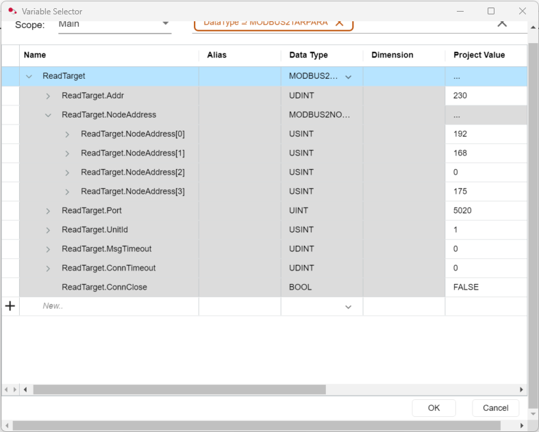
Click on the ReadTarget variable. Add these parameters.
-
Addr: Reference index. Set to 230 to tell the PLC to read values from this register. Note an offset of one compared to the robot's registers. In our case, we will receive the data on register 229 sent by the robot.
-
NodeAddress [0..3]: The target (Ned2 Robot) IP address split into 4 bytes (e.g., 192 . 168 . 0 . 175).
-
Port: TCP communication port. The default is 502 (the Ned2 Robot uses 5020).
-
UnitId: Slave/Server identification number. Usually set to 1.
-
MsgTimeout: Maximum wait time for a response (in ms). 0 = System default.
-
ConnTimeout: Time before an idle connection automatically closes (in ms). 0 = System default.
-
ConnClose: Boolean used to force-disconnect the socket (set to TRUE to reset).
Do not forget to click on ReadTarget before leaving the window.
For further information, check the documentation here. Another option is to select the Modbus and click F1.
The reading configuration is now finished. It is time to set up the writing side.
Add a new Rung. In the rung, add a new Modbus block or duplicate the previous one.
Add or change the name of the variables.
Click on the WriteLocal variable. Add these parameters.
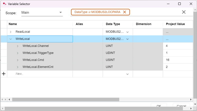
The only change is on the Modbus function code to configure Write Multiple Registers (16).
Do not forget to click on WriteLocal before leaving the window.
Click on WriteTarget.
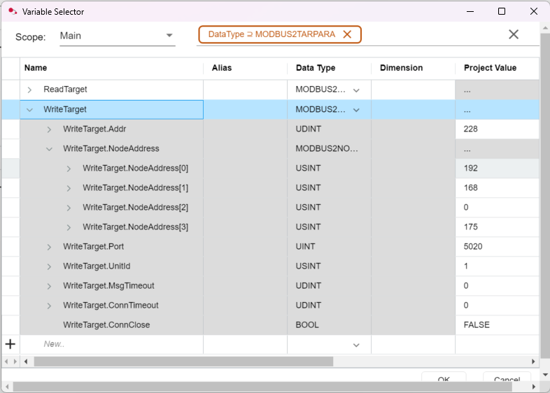
We can find the same parameters as the reading block. Only the register address changes. Also note an offset of one compared to the robot's registers. In our case, we will send command data to register 227 of the robot.
Do not forget to click on WriteTarget before leaving the window.
For further information, check the documentation by selecting the Modbus block and click F1.
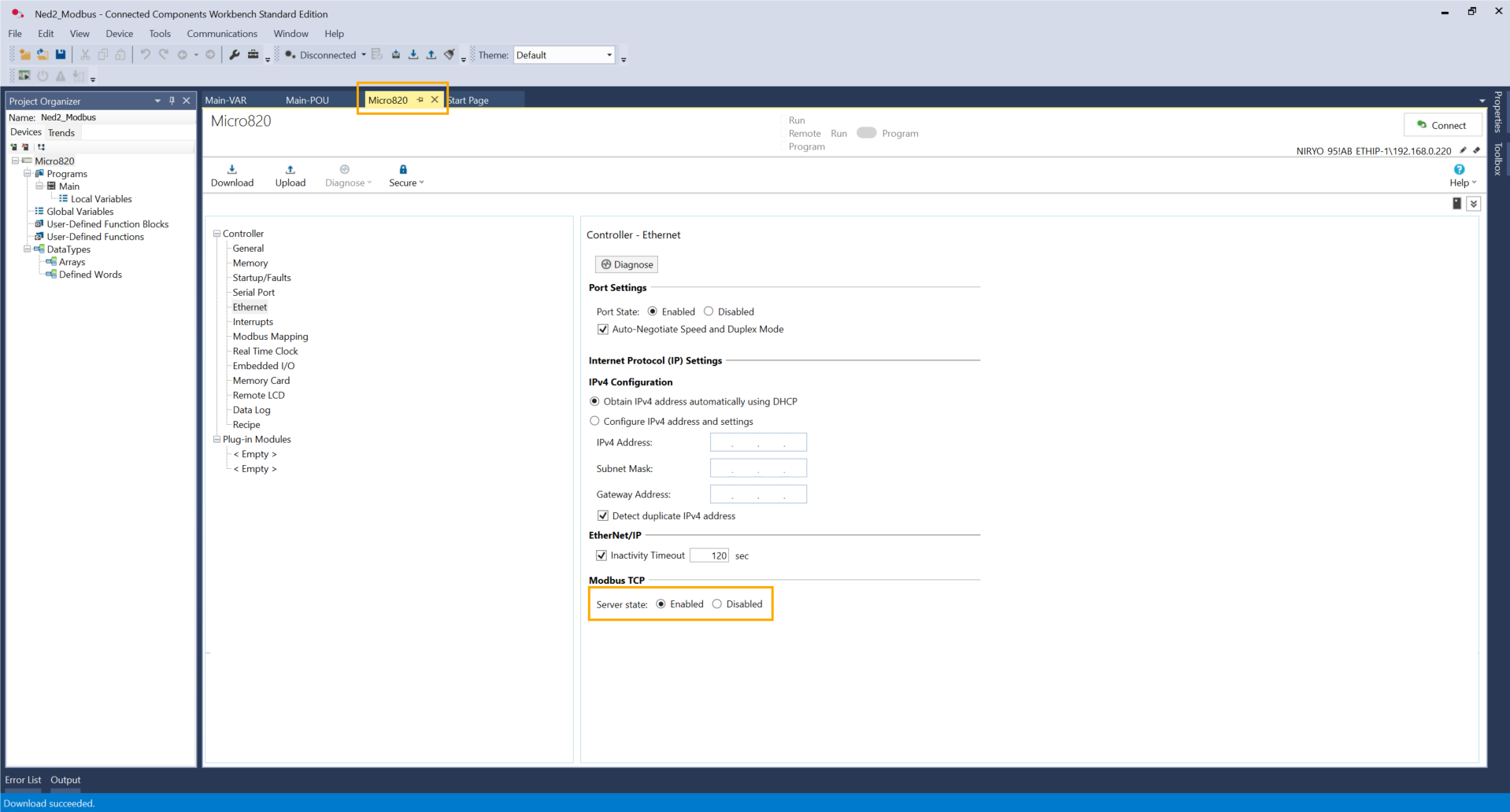
The code is now finished. Go to the Micro820 panel and to the Ethernet settings. Switch the Server State to Enabled.
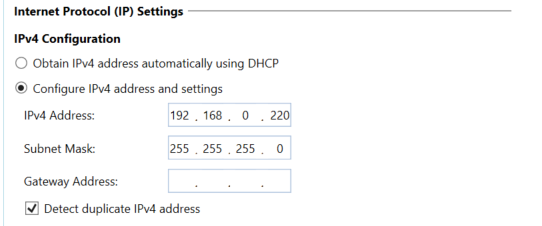
Another option is the IP Address can be configured manually by setting the same IP Address during the DHCP configuration.
Click on this icon to build the project.

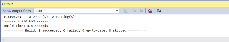
If the operation succeeds, click on the next icon to download the project.

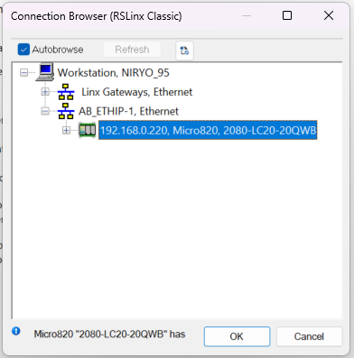
Select the PLC and click OK.
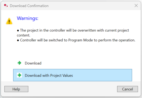
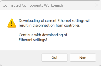
Click on Download with Project Values and click Yes.
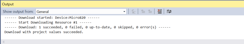
If the operation succeeds, move on to the next step.
Click on Connect.

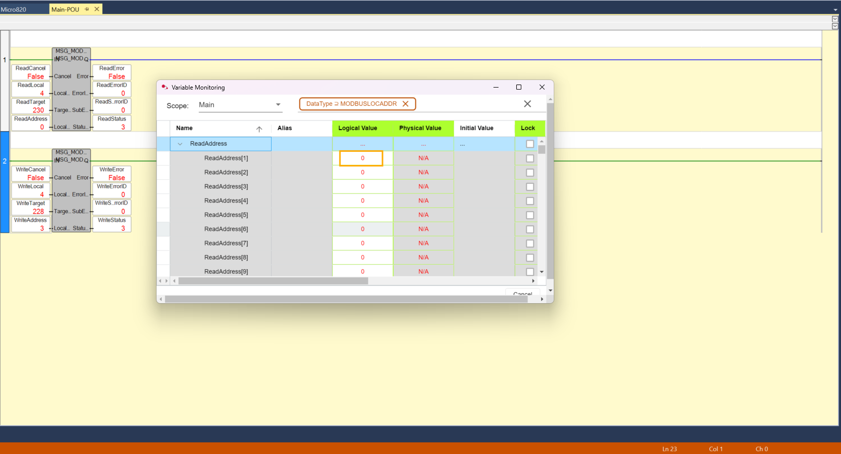
On the Main panel, click on WriteAddress. On the WriteAddress[1] line, set a value between 1, 2 and 3.
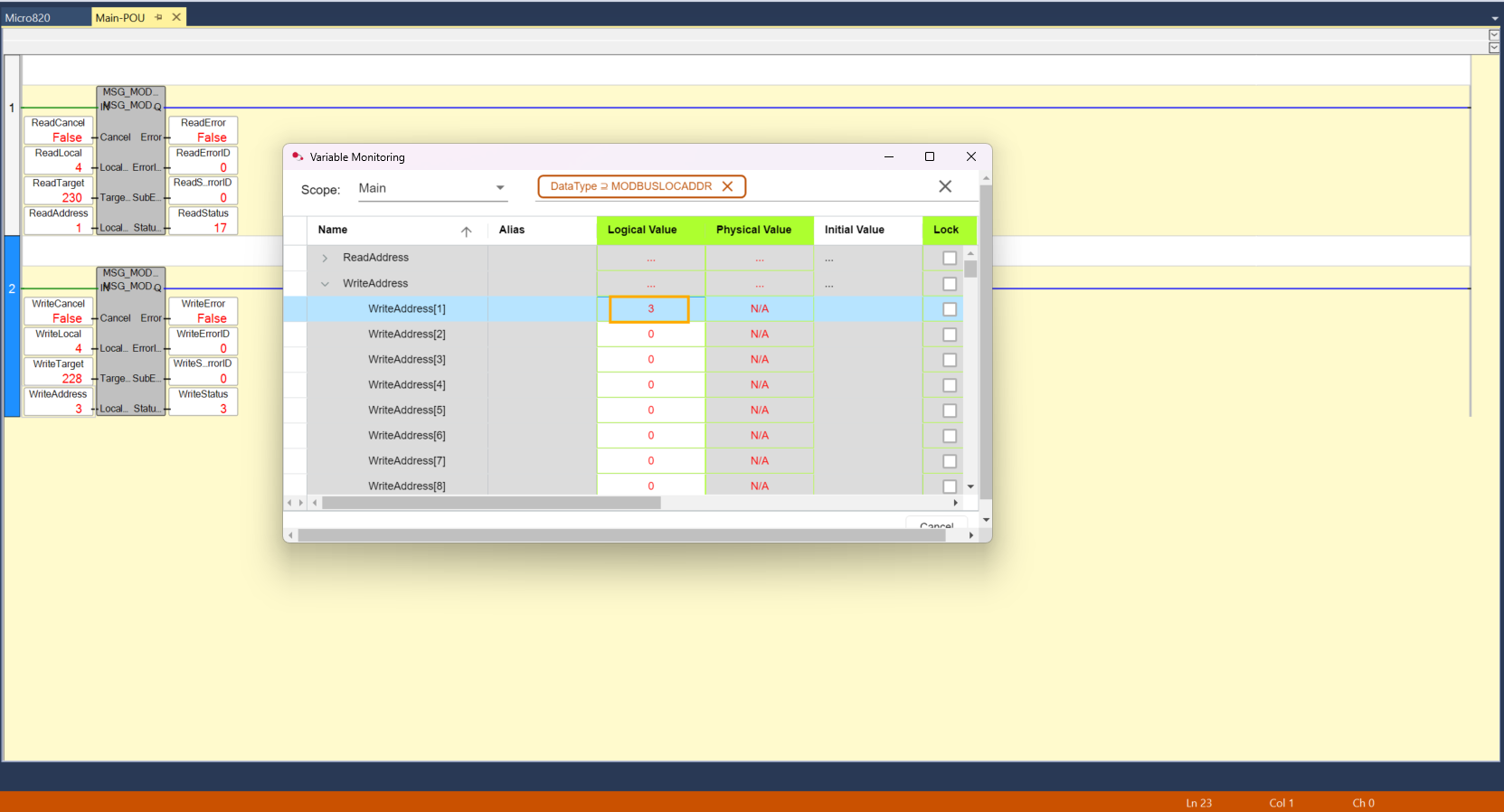
This value is now stored on the register, and it can be used to set conditions on it to activate some predefined actions. Let's see how it works on the robot's side.
Robot-side programming
It is time to create a program for the robot so it can receive commands from the PLC and send their status back. This program can be coded solely with PyNiryo. The version of PyModbus used is 3.9.0. To install it, type the following command in the terminal of a virtual Python environment.
pip install pymodbus==3.8.0Afterward, you can copy the example code, found here.
The Python script transforms the Niryo robot into a Modbus TCP client, which will listen to its own registers recorded on the robot's server. Its role is to listen to the orders sent by the PLC (commands) and send back information about its current state (status).
1. Addressing and Key Registers
The dialogue relies on two specific memory areas:
- REG_COMMAND (227): the "dashboard" where the PLC writes its orders (1, 2, etc.).
- REG_STATUS (229): the "mirror" where the robot writes its status (action in progress or finished) so the PLC can read it.
2. Command and status logic
The program runs in a loop according to this cycle:
-
Reading: the robot monitors register 227. If a new value appears, it launches the corresponding action (Home, Vision, or Trajectory).
-
Status: As soon as it begins, it writes 0 in register 229 (Busy). Once the movement is finished, it writes 1 (Ready).
The configuration on both the robot and PLC sides is done.
Testing
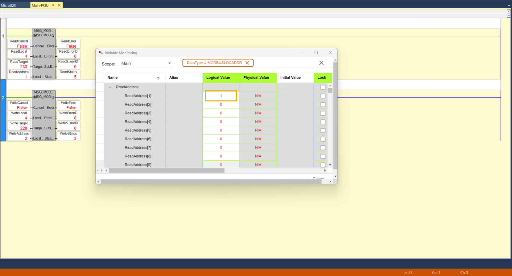
By updating the WriteAddress[1] value (1, 2, or 3), the corresponding status is displayed at ReadAddress[1], confirming that the state-defined value is correctly applied.
No action :
Action in progress :