Control via a Schneider PLC and Machine Expert Basic (Modbus)
Interface configuration on Machine Expert Basic
On the computer, open the Machine Expert Basic software.
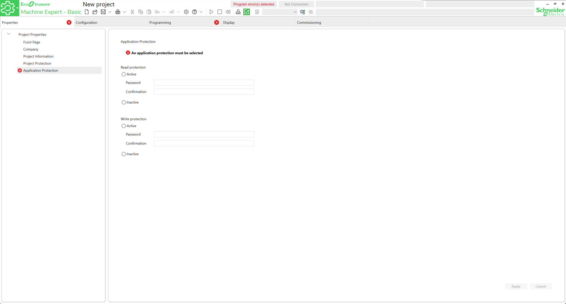
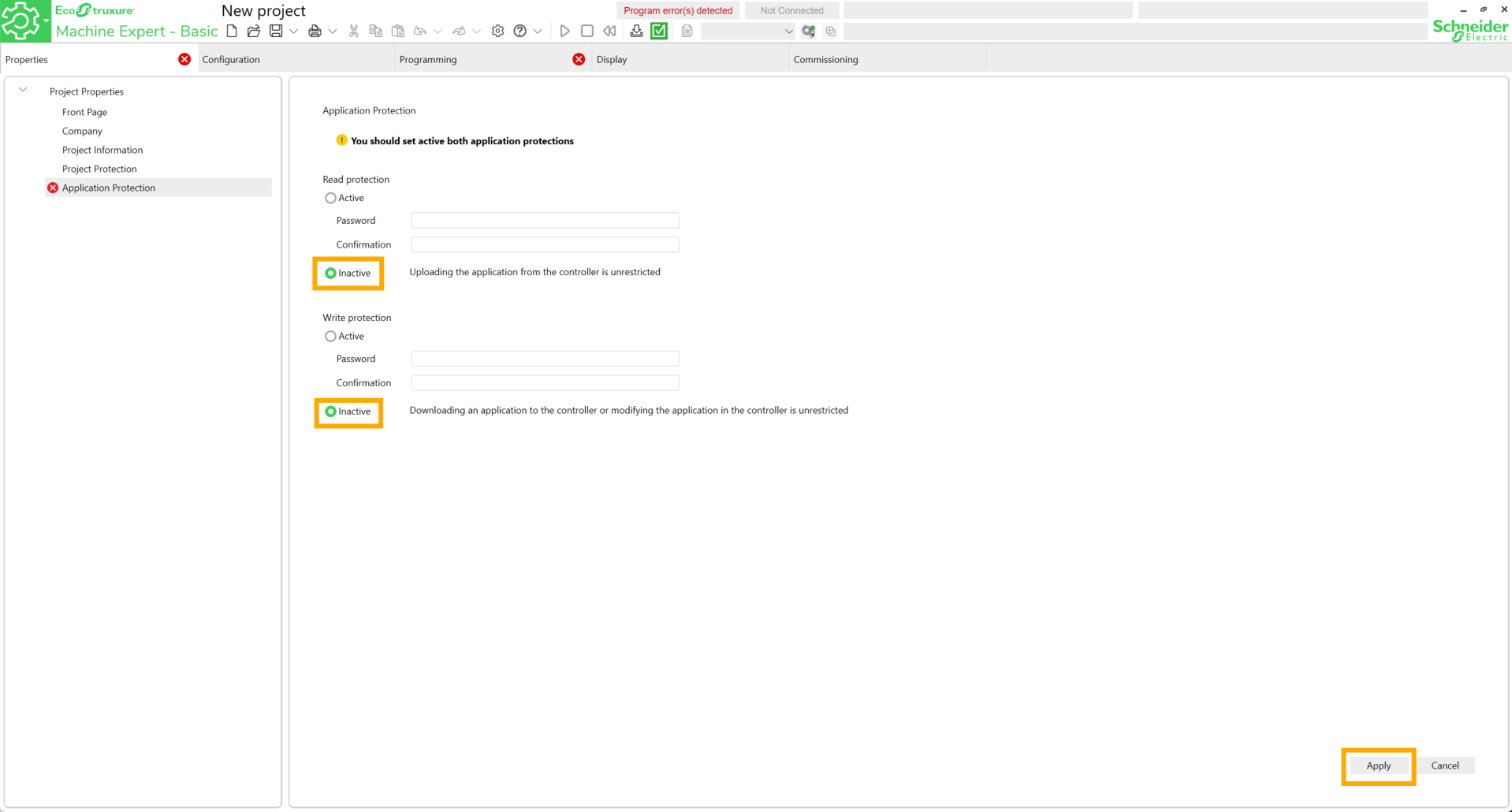
First, configure a password for both types of protections. For ease of use, set the protections to Inactive then click Apply.
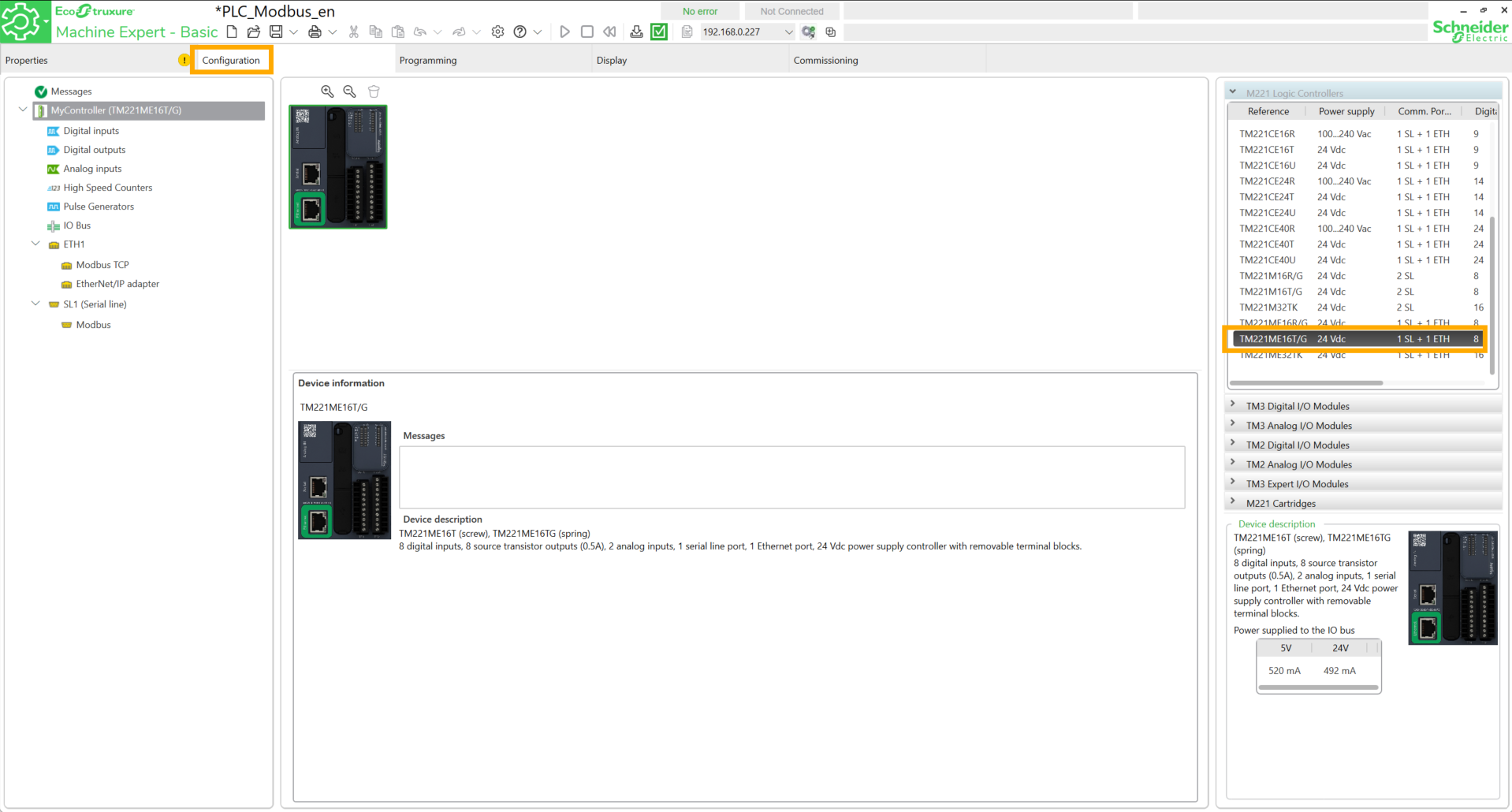
Go to the Configuration tab and search for the PLC reference.
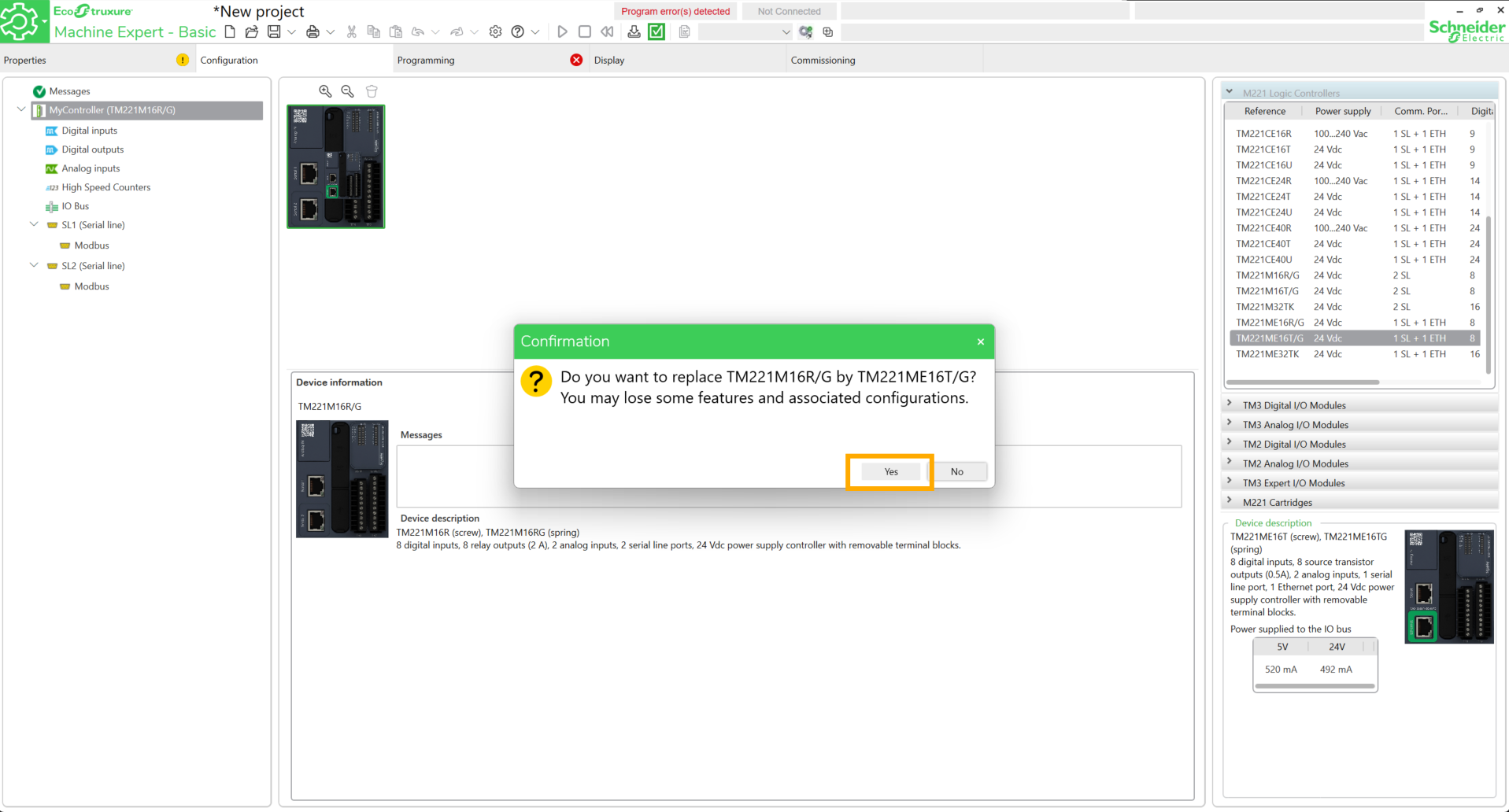
Drag and drop the block onto the workspace and click Yes.
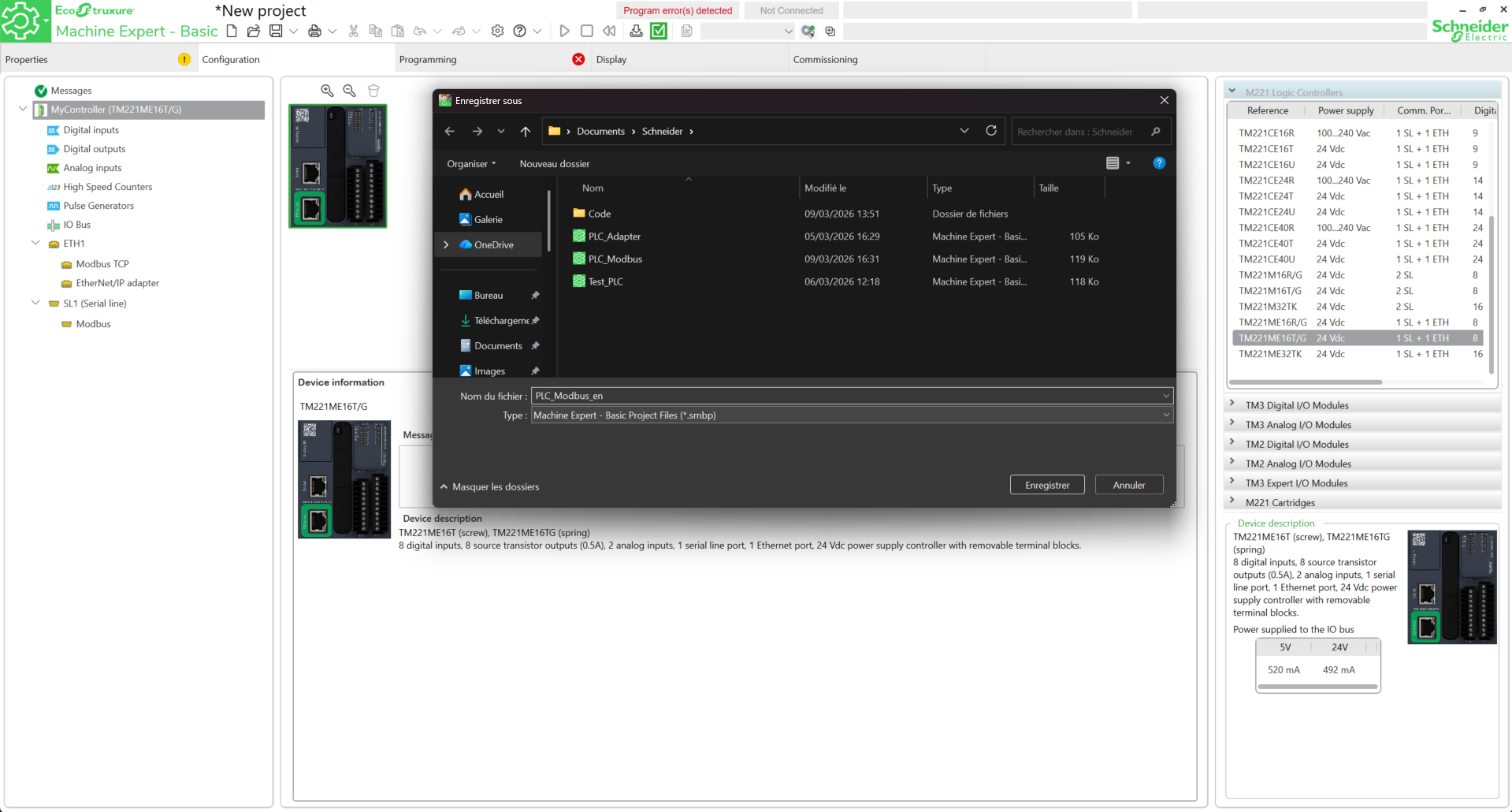
Save the project.
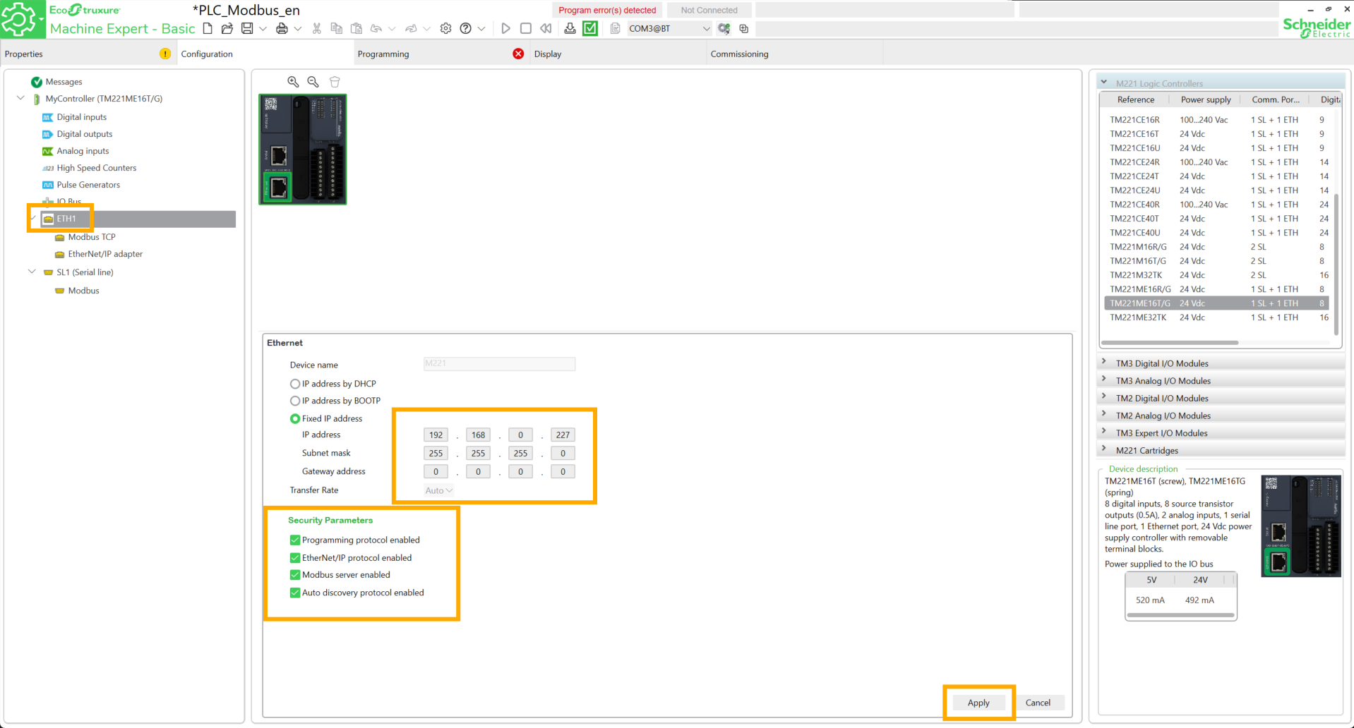
Go to ETH1, configure an available IP address, check the four boxes below and click Apply.
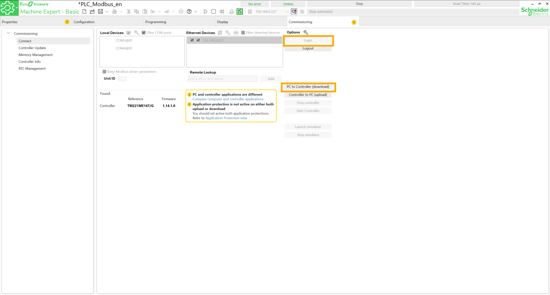
Go to the Commissioning tab. The IP address entered previously must appear in the Ethernet Devices field. To verify the connection to the PLC, check the boxes near the IP address, then click on it and finally click Login.
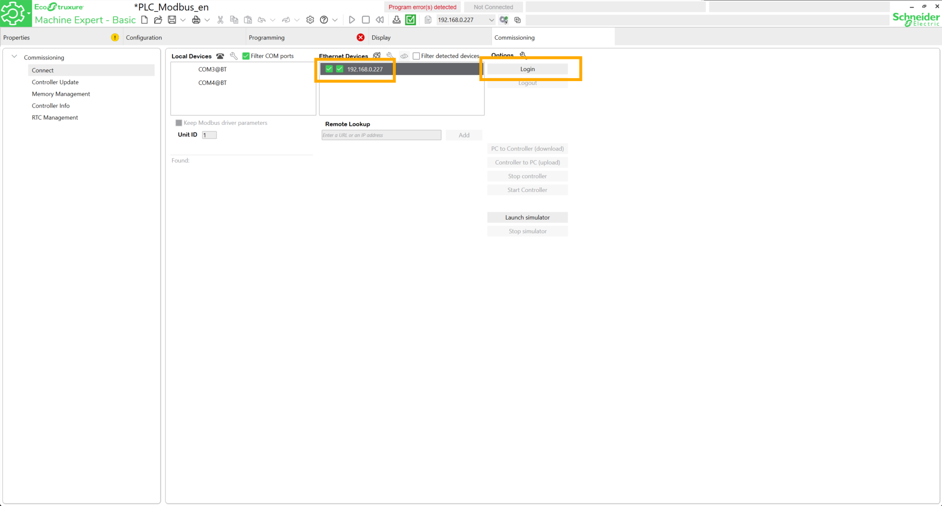
If the connection is successful, the mention Online must appear.

Click Logout.
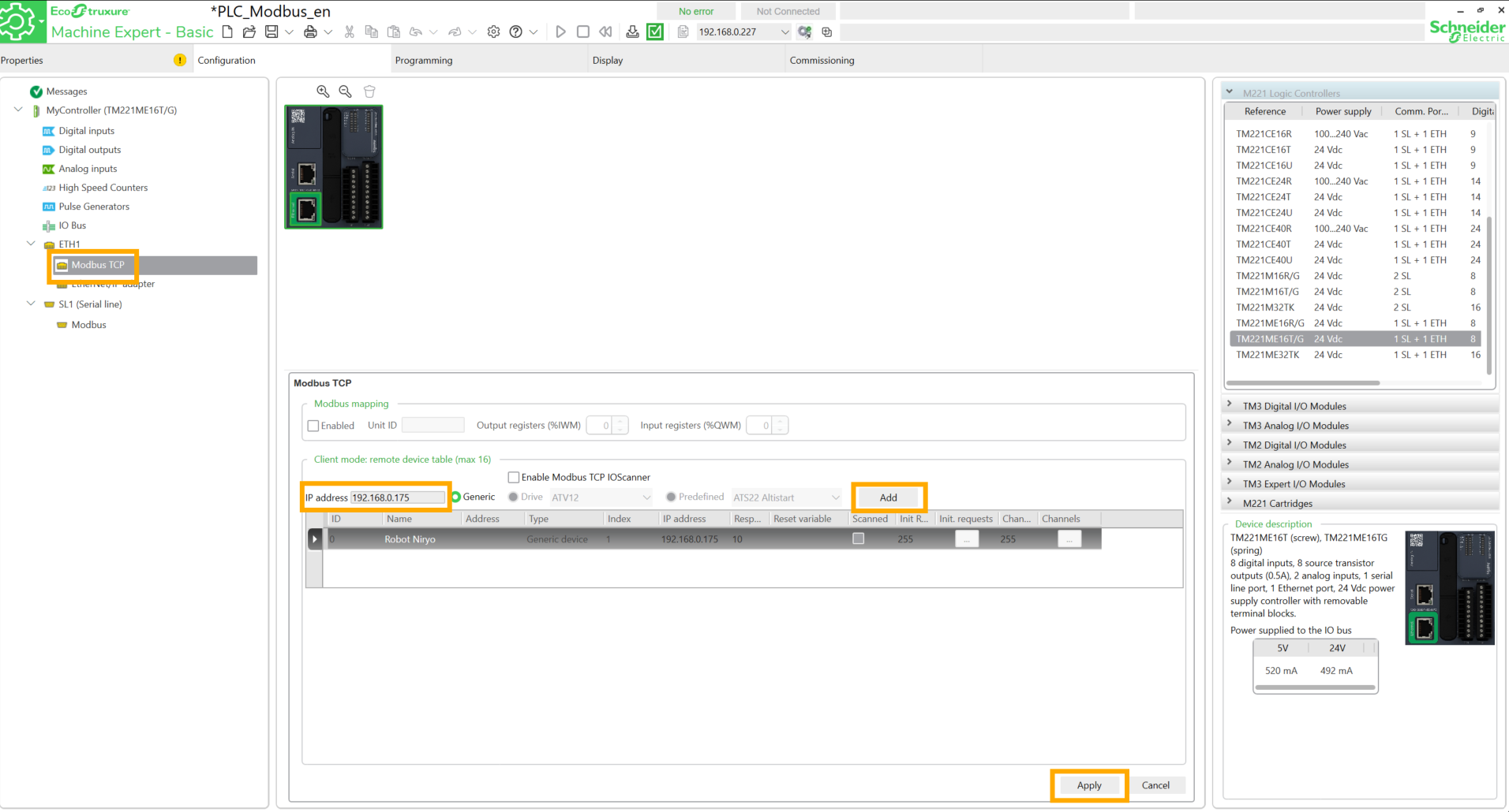
Return to the Configuration tab and to Modbus TCP. Add the static IP address of the robot. To define a static address, follow the tutorial here. Click Add, choose a name and click Apply.
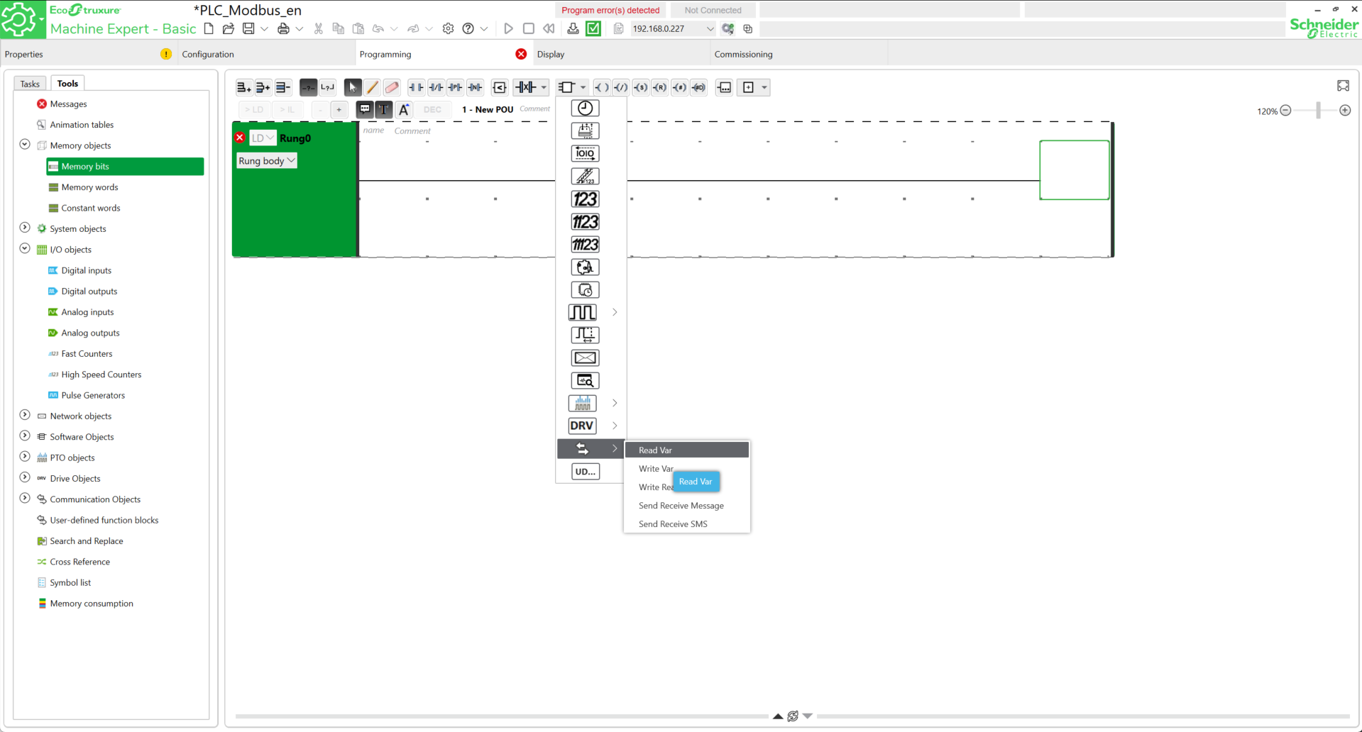
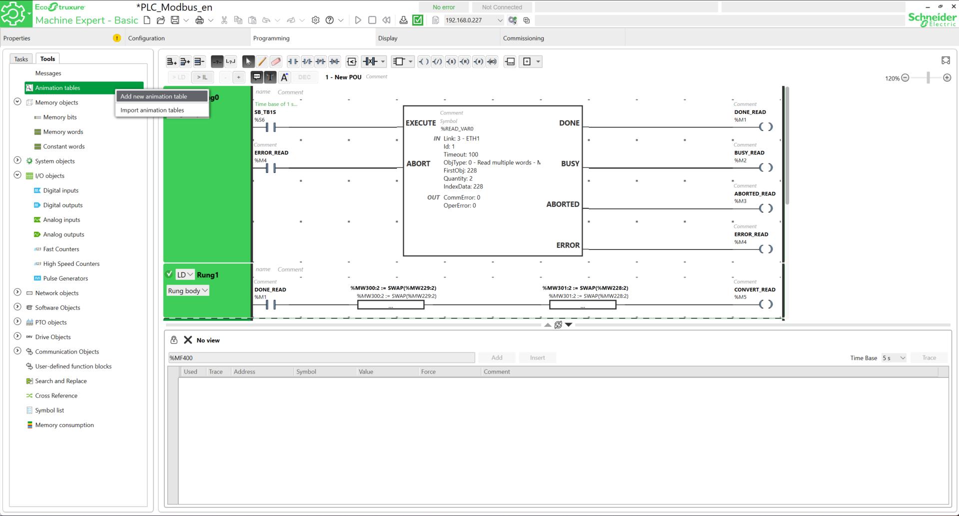
Go to Programming. This first part will focus on data reading. Add the Read Var block.
Add the following parameters into the block.
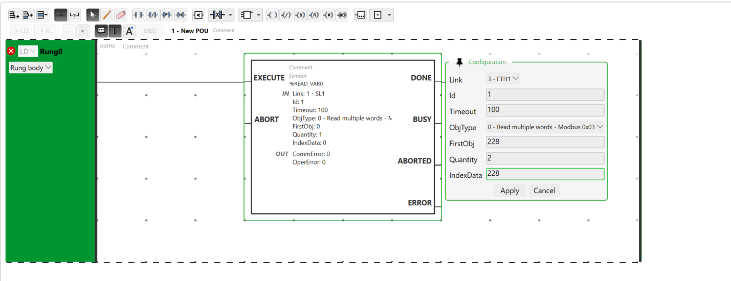
READ_VAR block (Rung 0):
- Link: 3 - ETH1
-
OBJTYPE: 0 - Read multiple words (To read register values)
-
FirstObj: starting address in the robot (ex: 228). Note an offset of one compared to the robot's registers. In our case, we will receive the data on register 229 sent by the robot.
-
Quantity: 2 (to read a float).
-
IndexData: %MW228 (reception address in the PLC).
Click Apply.
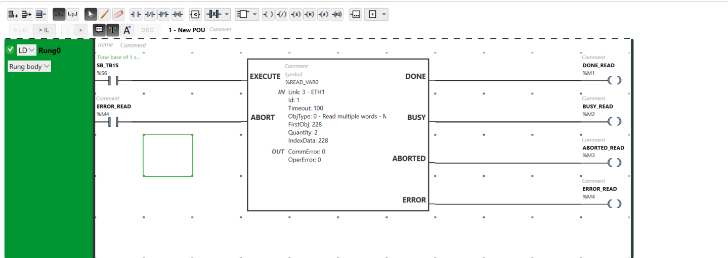
Add contacts to the block inputs and coils to its outputs. Assign addresses and symbols to the different pins:
| Pin | EXECUTE | ABORT | DONE | BUSY | ABORTED | ERROR |
| Symbol | SB_TB1S | ERROR_READ | DONE_READ | BUSY_READ | ABORTED_READ | ERROR_READ |
| Address | %S6 | %M4 | %M1 | %M2 | %M3 | %M4 |
The addresses and symbols presented here are given as an indication. Feel free to adapt this choice according to different standards. Also note that the clock address is modifiable (for example by using %S7) to match your system configuration.
Add a new network. In this one, add a new contact, two operation blocks and a new coil. The operation blocks will be used to proceed with a data conversion.
Indeed, the robot and the PLC do not speak the same binary "dialect" for floating-point numbers (Floats/REAL). The robot sends information in a reversed order compared to what the M221 PLC expects. Without this step, inconsistent values such as 9.10844E-44 could be read instead of 8.0.
Role of the two operation blocks (Read Mode)
The goal is to put the 32 bits of data back in the correct order before the PLC interprets them.
-
The "Word Swap":
-
The float is split into two 16-bit registers (%MW228 and %MW229).
-
The operation consists of using two new registers (%MW300 and %MW301), moving the content of the second word to the first, and vice versa, to place the exponent and the mantissa in the right place. The float is therefore swapped.
-
-
The "Byte Swap":
-
Inside each word, the two bytes (8 bits) are also swapped.
-
The SWAP function (or ROL ..., 8) switches these bytes so that the PLC finally reads the real value.
-
Conversion steps
-
Reception: the %READ_VAR0 block saves the raw data "out of order" in %MW228 and %MW229.
-
Triggering: once the reading is finished without error, the %M1 bit (DONE) activates and authorizes the execution of calculations.
-
Processing: The instructions %MW300:2 := SWAP(%MW229:2) and %MW301:2 := SWAP(%MW228:2) process both words at once. They swap the bytes and store the result in new clean areas: %MW300 and %MW301.
-
Result: the PLC automatically assembles these two words to form the variable %MF300 (%MW300 and %MW301). This is where the corrected value is read (ex: 1.0 or 8.0).
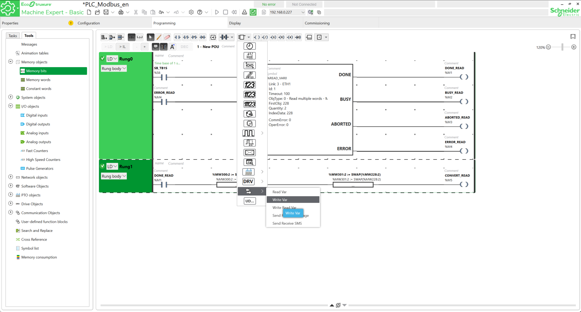
Add the expressions as well as the addresses and symbols as shown in the following image.

The reading block is finally ready. For the writing part, the same logic will be applied.
Add a new network and search for the Write Var block.
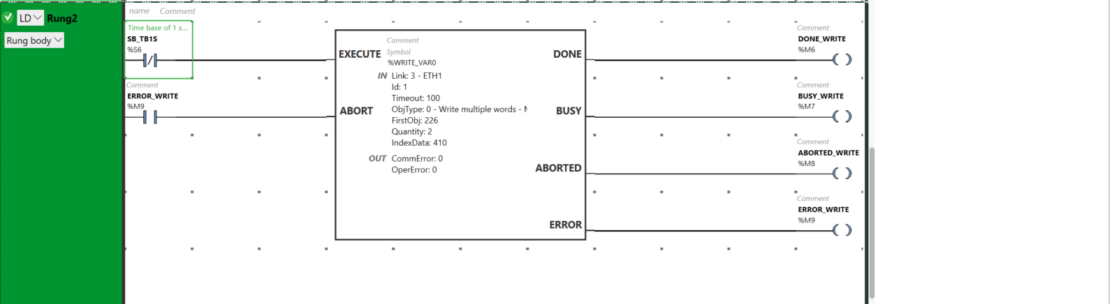
Add the different blocks in the same way as shown in the image with the corresponding addresses and symbols.
| Pin | EXECUTE | ABORT | DONE | BUSY | ABORTED | ERROR |
| Symbol | SB_TB1S | ERROR_WRITE | DONE_WRITE | BUSY_WRITE | ABORTED_WRITE | ERROR_WRITE |
| Address | %S6 | %M9 | %M6 | %M7 | %M8 | %M9 |
Add the following parameters into the block.
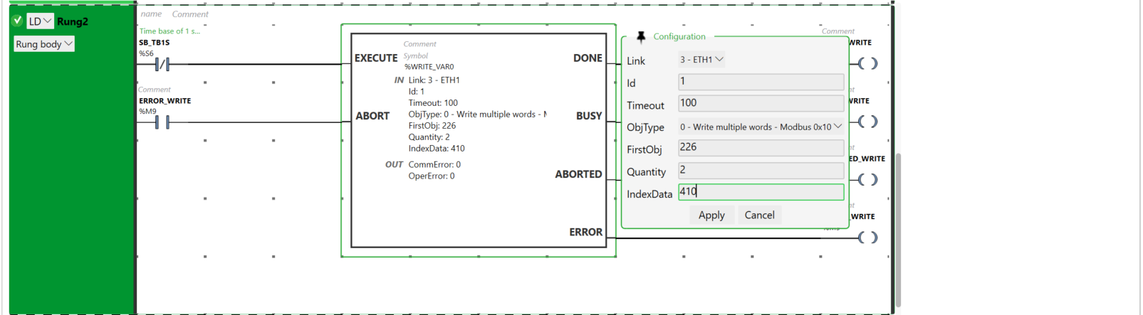
WRITE_VAR block (Rung 0):
- Link: 3 - ETH1
- Id :
- Timeout :
-
OBJTYPE: 0 - Write multiple words (To send values to registers)
-
FirstObj: starting address in the robot (ex: 226). Also note an offset of one compared to the robot's registers. In our case, we will send command data to register 227 of the robot.
-
Quantity: 2 (to read a float).
-
IndexData: %MW226 (reception address in the PLC).
Click Apply.
In the same way as the reading part, add a new network with a new contact, two operation blocks and a new coil.

Role of the two operation blocks (Write Mode)
The goal is to intentionally "scramble" the 32 bits of the setpoint so they arrive in the format expected by the robot.
-
The "Word Swap": we prepare the sending by crossing the registers of the setpoint (ex: %MW400 and %MW401) toward the sending registers (%MW410 and %MW411).
-
The "Byte Swap": the SWAP function pre-swaps the bytes of each word so that the robot receives the exponent and mantissa bits in its own "dialect".
Conversion steps
-
Preparation: enter the target value in the floating variable %MF400 (composed of %MW400 and%MW401).
-
Processing: the instructions %MW410:2 := SWAP(%MW401:2) and %MW411:2 := SWAP(%MW400:2) (with swapping the word order) prepare the data in the buffer registers %MW410 and %MW411.
-
Triggering: the activation of the %WRITE_VAR0 block (via a button or a clock) launches the transfer.
-
Sending: the PLC transmits the "pre-crossed" data to the robot which then interprets them instantly as the correct real value.
The configuration is ready.
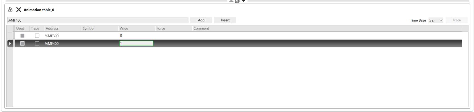
Before loading it into the PLC, create an animation table to display the read values and modify the values to be written.
To do this, right-click on Tools → Animation tables → Add a new animation table.
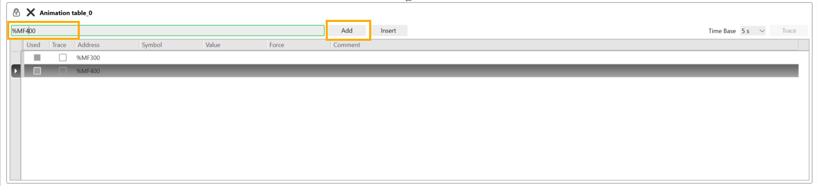
Enter the addresses %MF300 (Read) and %MF400 (Write) one by one by clicking Enter or the Add button each time.
Go to Commissioning. Click Login then PC to Controller (download). Confirm to overwrite the program.
 Return to Programming. Click the button to Start Controller.

Double-click on the value cell of the address. This value will be used in the robot program to execute predefined actions.
The PLC-side configuration is now complete.
Modifying the Modbus port
Although the standard port for the Modbus protocol is 502, Niryo robots use port 5020 by default. The Machine Expert – Basic software does not allow customization of the communication port (unlike "Pro" versions or TIA Portal), so an adaptation is necessary. To overcome this limitation, a port forwarding rule must be configured directly on the robot.
To do this, on Windows (also applicable to Linux and Mac), open the command prompt and connect to the robot via SSH. The steps are explained here. The IP address to provide is that of the robot, configured earlier when adding it to Machine Expert - Basic.
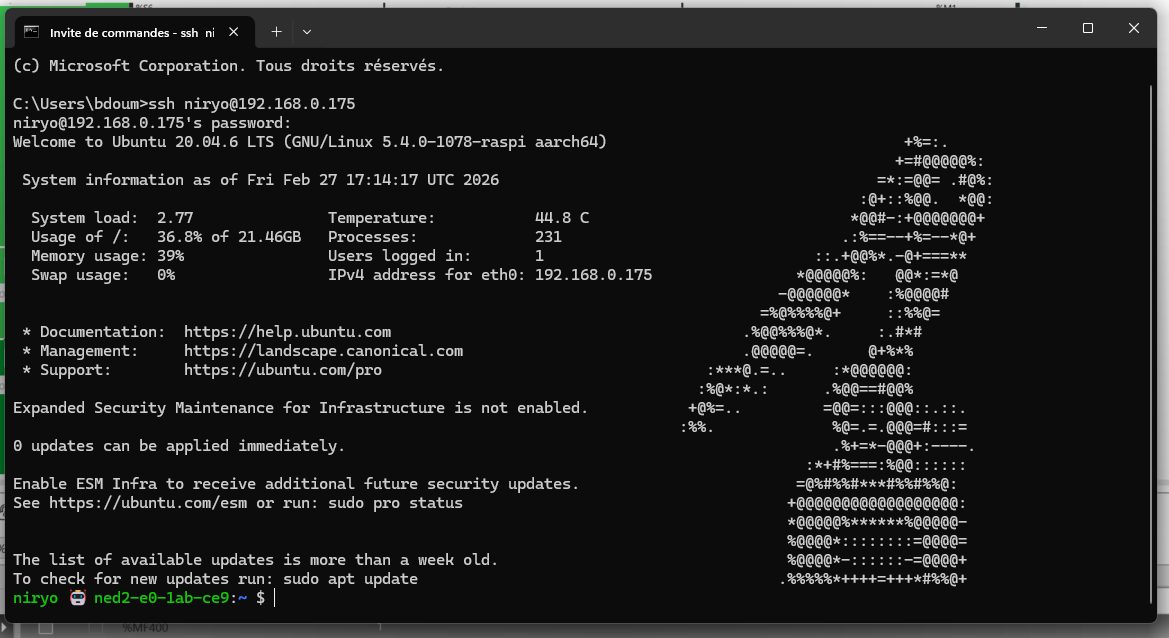
Once the connection is made, type line by line:
cd /etc/ufw
sudo nano before.rules
Enter the same password as used for the SSH connection. In this file, add the following lines before COMMIT:
COMMIT
### PORT FORWARDING ###
*nat
:PREROUTING ACCEPT [0:0]
-A PREROUTING -p tcp --dport <PORT> -j REDIRECT --to-port 5020
Replace "<PORT>" with the desired port number (502).
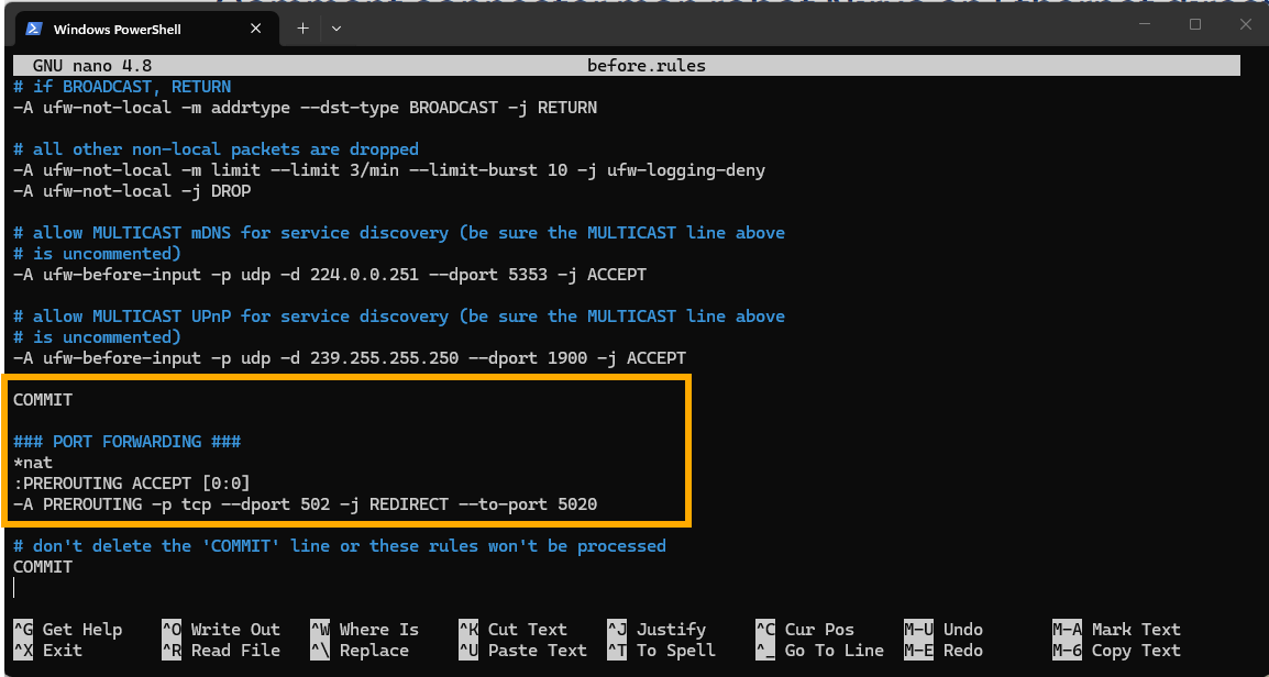
Save by pressing CTRL+S then close the file with CTRL+X.
Next, type the following commands:
cd
cd /etc/default
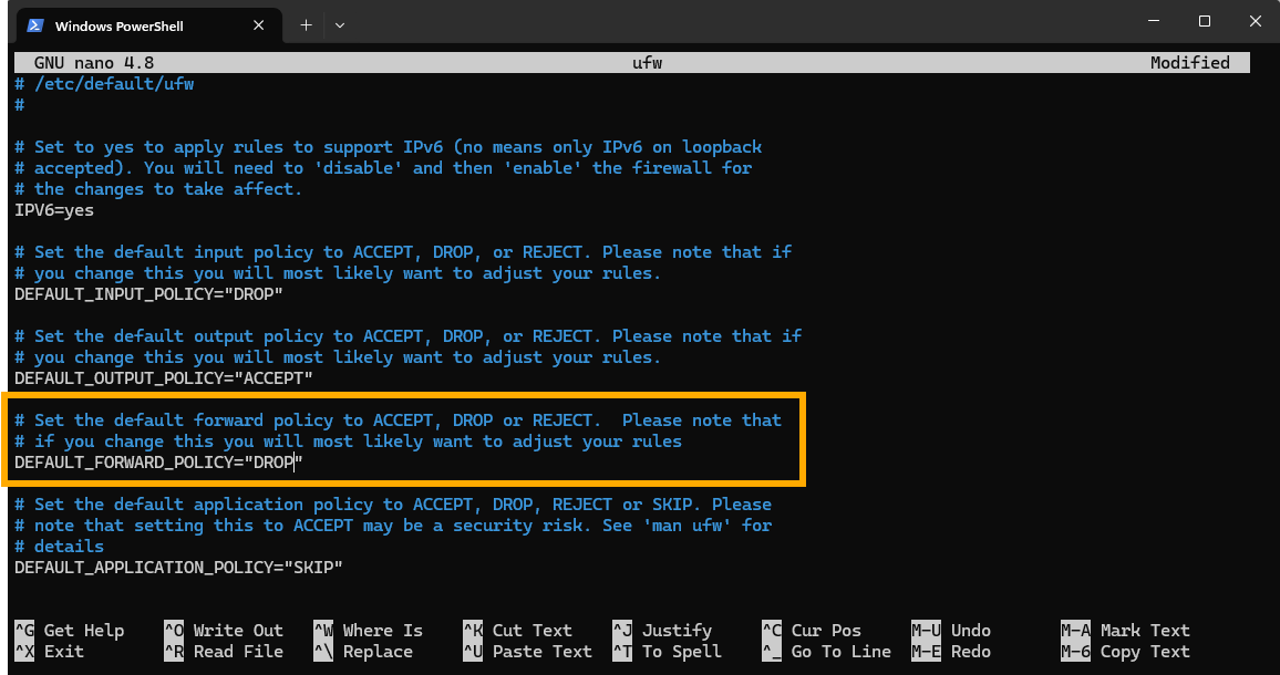
sudo nano ufw
Then, at the DEFAULT_FORWARD_POLICY line, change from DROP to ACCEPT.
Save by pressing CTRL+S then close the file with CTRL+X.
Type the following command:
sudo ufw enableIf errors occur when launching this command (unstable behavior observed with ufw), edit the before.rules file: delete and then re-insert the COMMIT tag located just before the line ### PORT FORWARDING ###.
Retry the command above, then if no error appears, type the following command:
sudo ufw reloadIf everything worked, deactivate the SSH connection.
sudo reboot
Robot-side programming
It is time to create a program for the robot, so it can receive commands from the PLC and send their status back. This program can be coded solely with PyNiryo. The version of PyModbus used is 3.9.0. To install it, type the following command in the terminal of a virtual Python environment.
pip install pymodbus==3.8.0Afterwards, you can copy the example code, found here.
The Python script transforms the Niryo robot into a Modbus TCP client which will listen to its own registers recorded on the robot's server. Its role is to listen to the orders sent by the PLC (commands) and send back information about its current state (status).
1. Addressing and Key Registers
The dialogue relies on two specific memory areas:
- REG_COMMAND (227): the "dashboard" where the PLC writes its orders (1.0, 2.0, etc.).
- REG_STATUS (229): the "mirror" where the robot writes its status (action in progress or finished) so the PLC can read it.
2. The role of Decoding/Encoding
Since the PLC and the robot do not use the same byte order, the script uses two vital functions:
-
decode(): receives the "scrambled" registers sent by the PLC and reshapes them into a real number (ex: transforms PLC signals into 2.0).
-
encode() : prepares the robot's status data (ex: 1.0 for "finished") in the inverse format so the PLC can read them correctly without error.
3. Command and status logic
The program runs in a loop according to this cycle:
-
Reading: the robot monitors register 227. If a new value appears, it launches the corresponding action (Home, Vision, or Trajectory).
-
Status: as soon as it begins, it writes 0.0 in register 229 (Busy). Once the movement is finished, it writes 1.0 (Ready).
The configuration on both robot and PLC side is done.
Tests
Return to Machine Expert Basic, click on Login, then start the controller. Launch the program on the robot side, then vary the value of the address %MF400 in the animation table to see the robot move.
