Control via a Schneider PLC and Machine Expert Basic (I/O adapter)
Tutorial
Electrical diagram:
In this first phase of the tutorial, we will see how to connect the I/O Adapter with the Siemens PLC on one side and the Ned2 robot on the other. For this, a power supply that can provide 24 V is necessary (to power the I/O Adapter). We power the PLC outputs with its own 24V (cable connecting L+ to 1L). Here are the connections to follow:

Interface configuration on Machine Expert Basic
On the computer, open the Machine Expert Basic software.
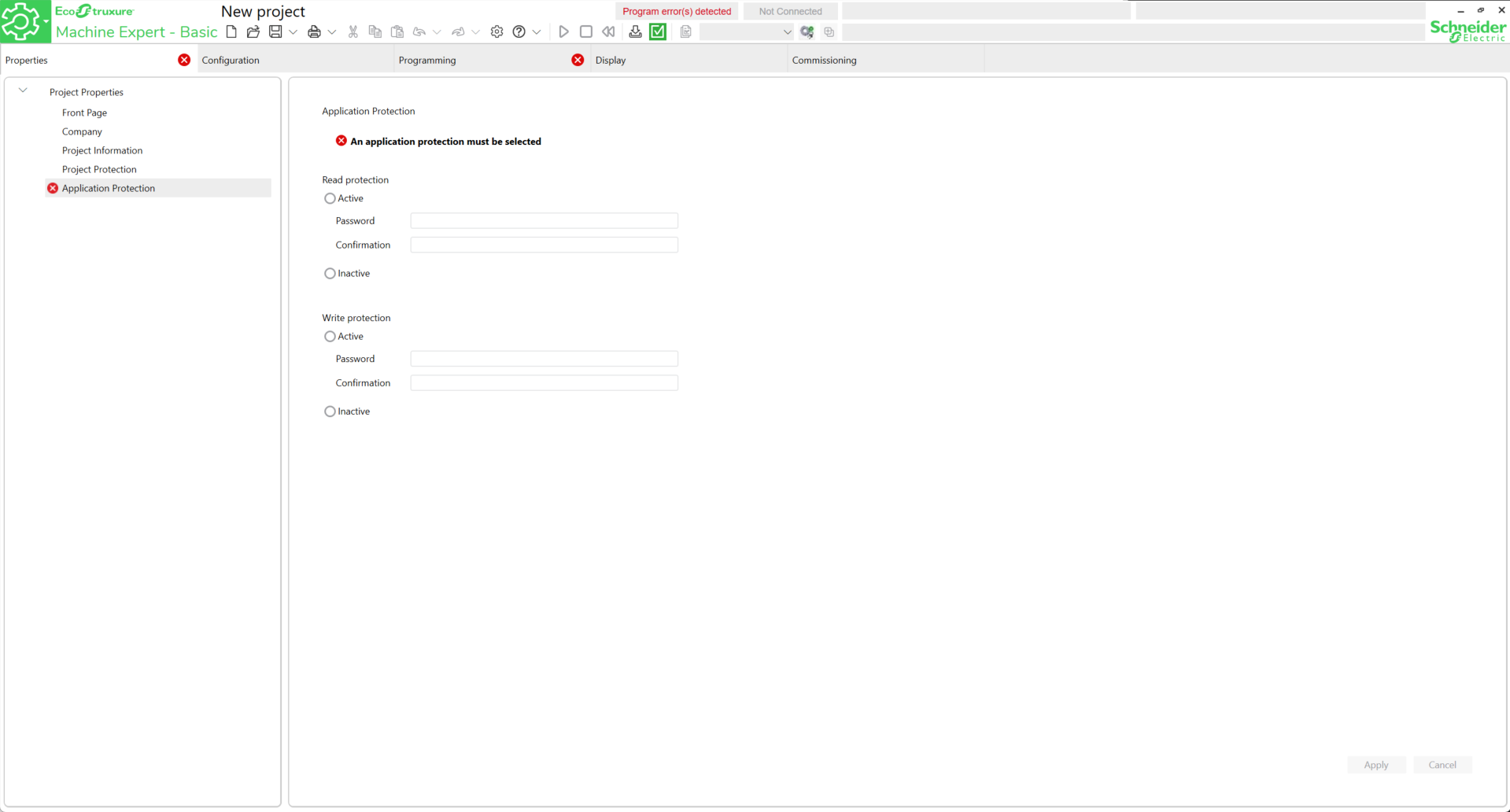
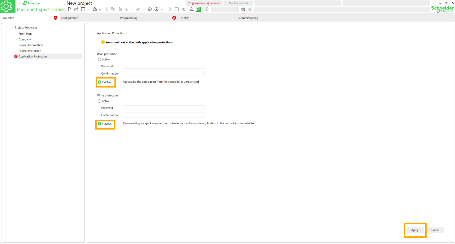
First, configure a password for both types of protections. For ease of use, set the protections to Inactive then click Apply.
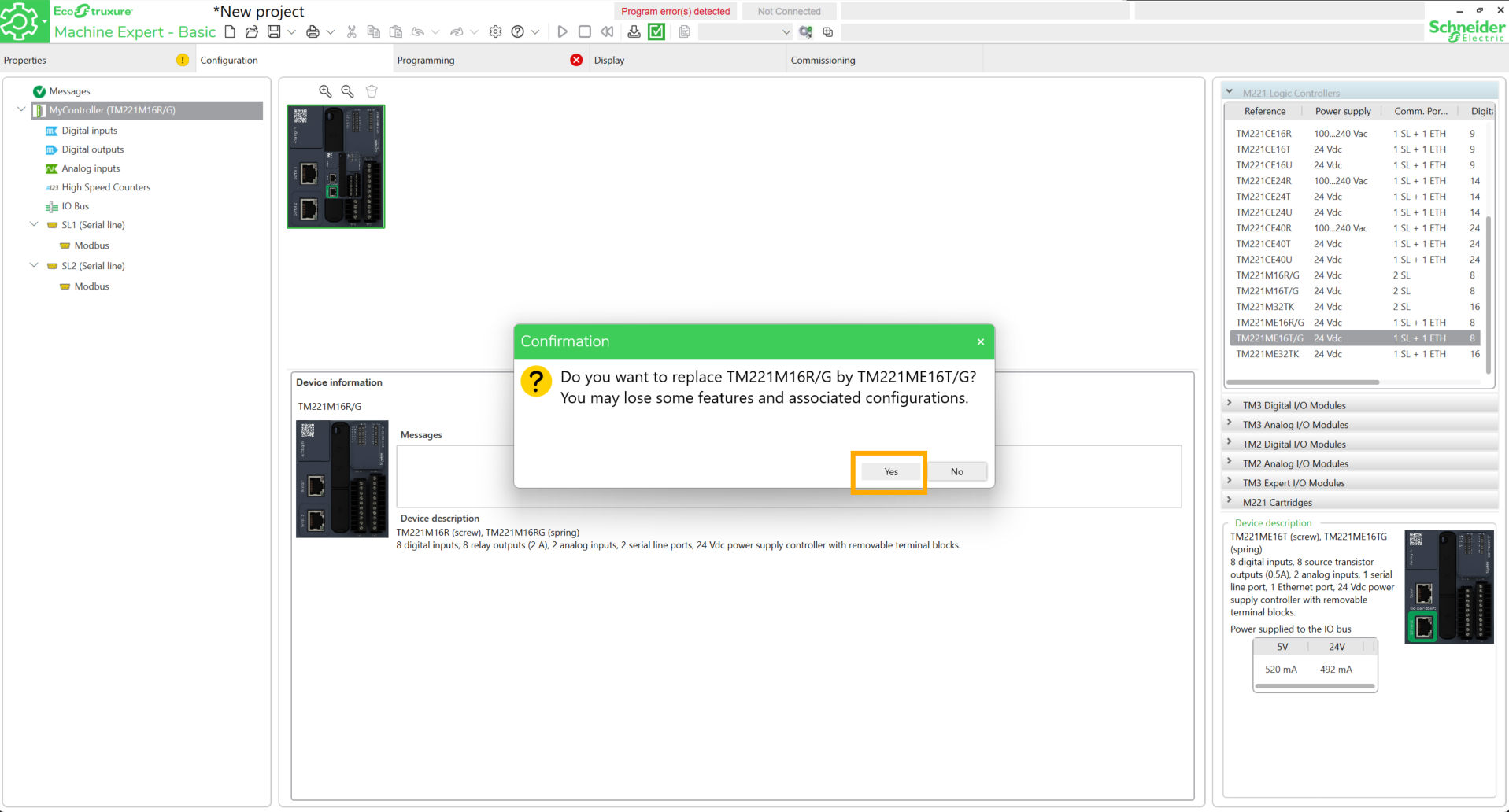
Go to the Configuration tab and search for the PLC reference.
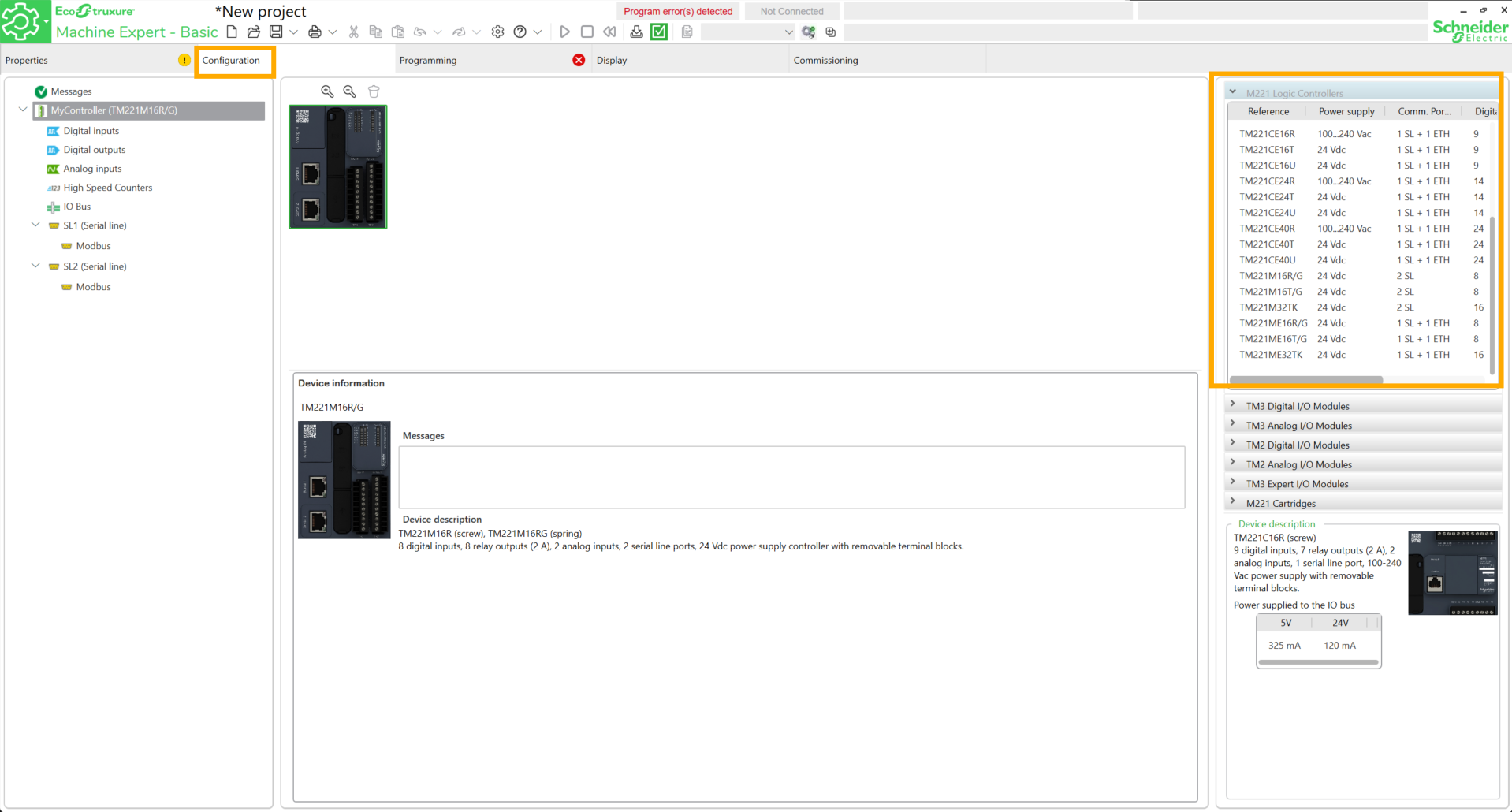
Drag and drop the block onto the workspace and click Yes.
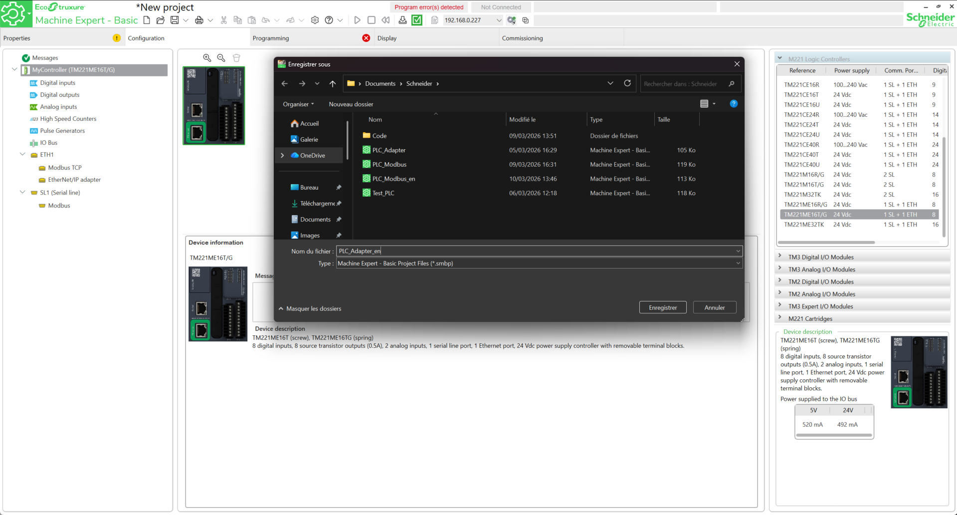
Save the project.
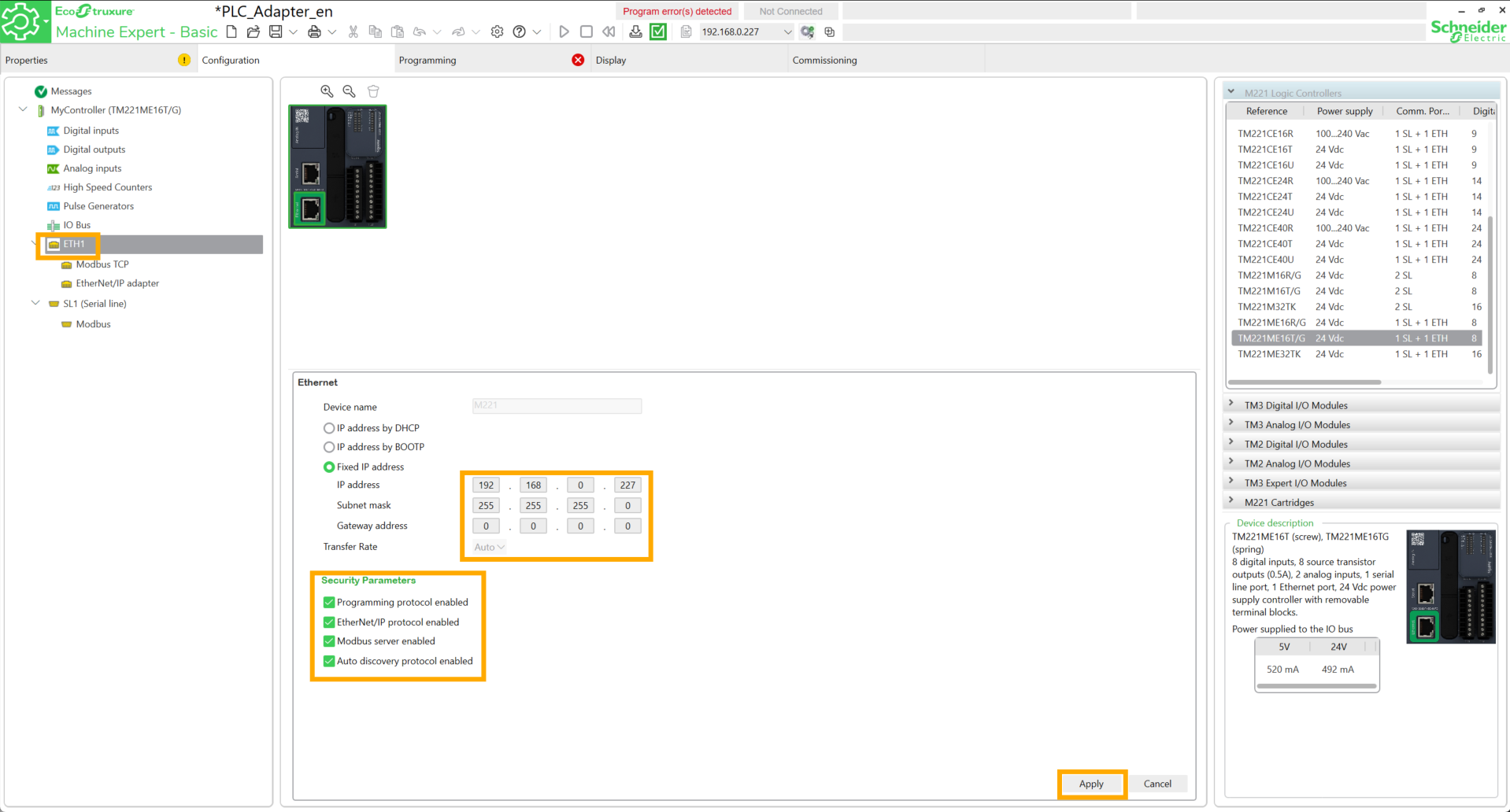
Go to ETH1, configure an available IP address, check the four boxes below and click Apply.
Go to the Commissioning tab. The IP address entered previously must appear in the Ethernet Devices field. To verify the connection to the PLC, check the boxes near the IP address, then click on it and finally click Login.
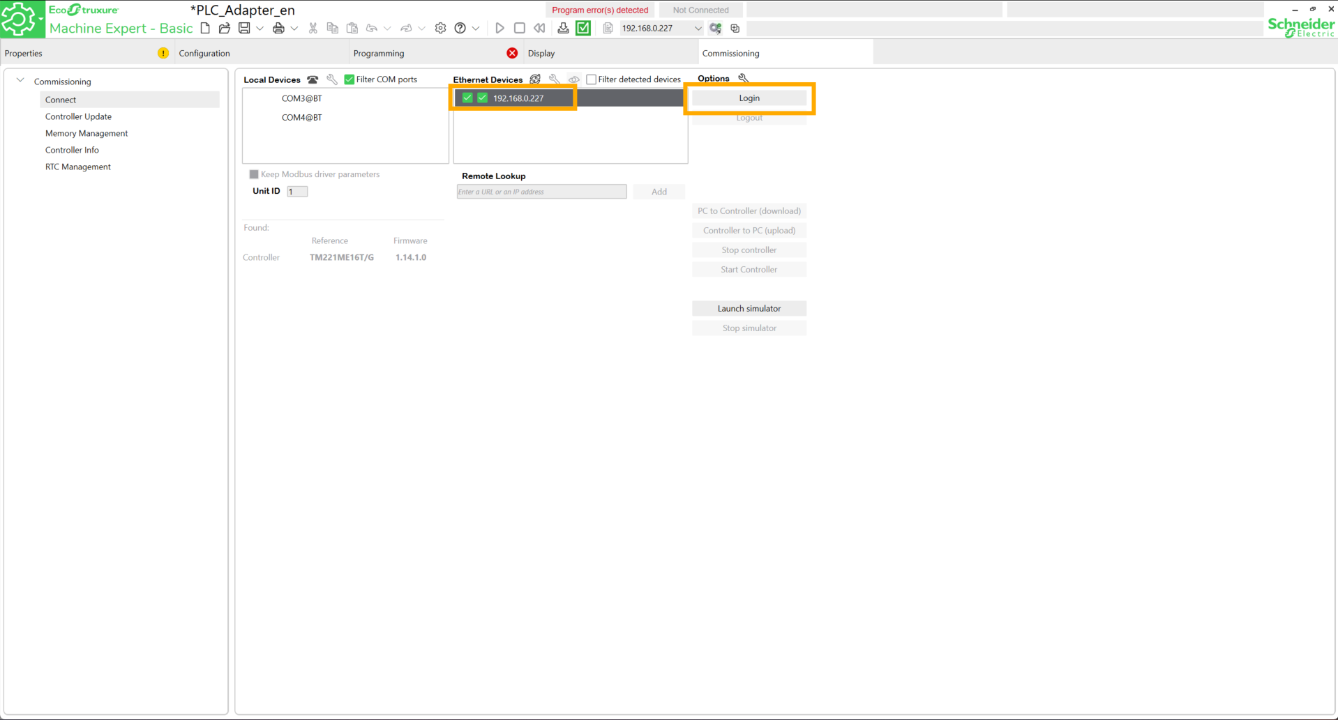
If the connection is successful, the mention Online appears.

Click on Logout.
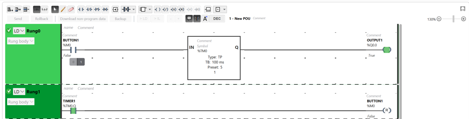
Go to the Programming tab. In the next steps, we will create Ladder code simulating physical push buttons.
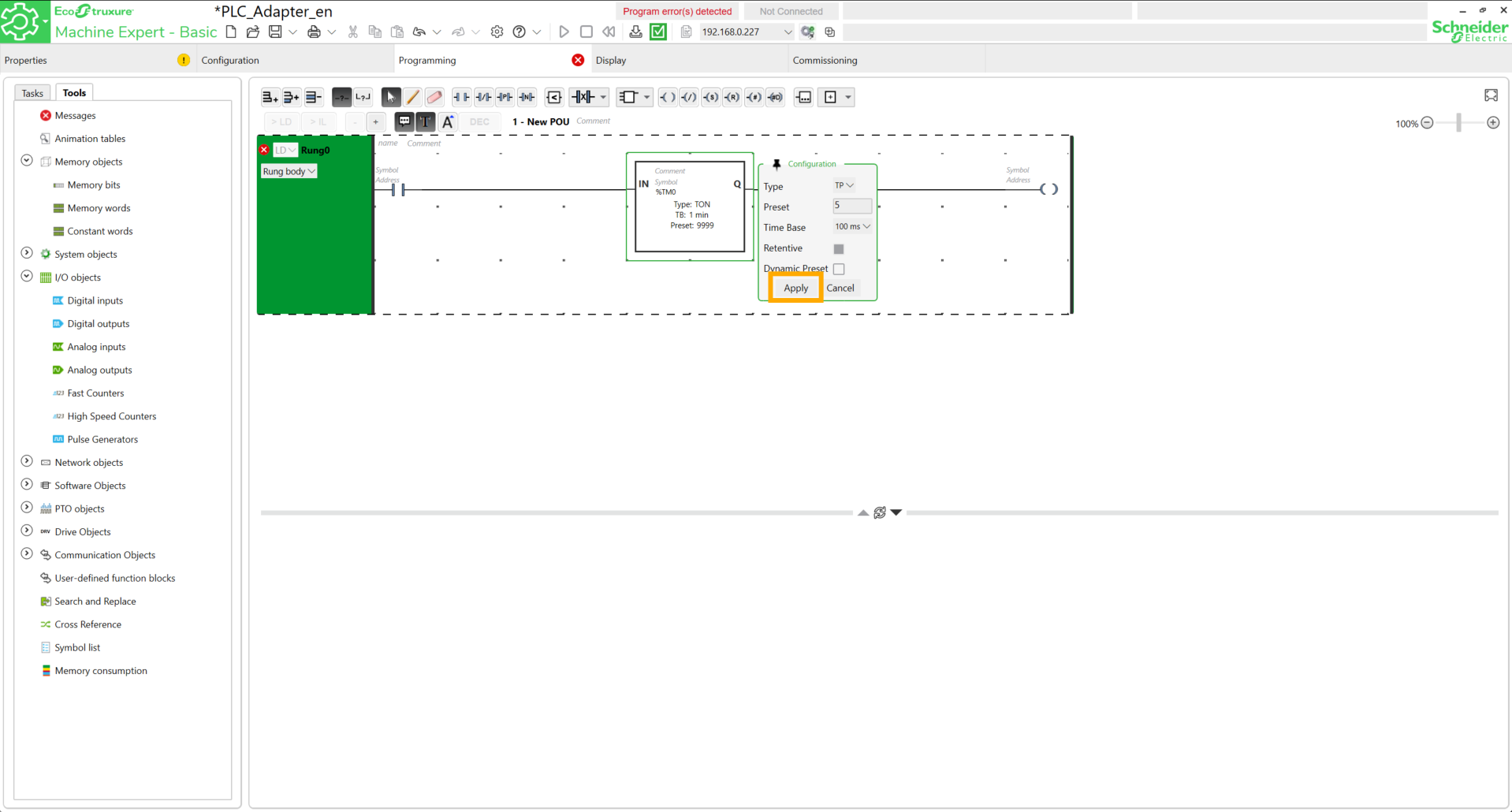
To do this, add a contact, a timer block, and a coil on Rung0. Configure the timer block to 500ms in TP mode. Click Apply.
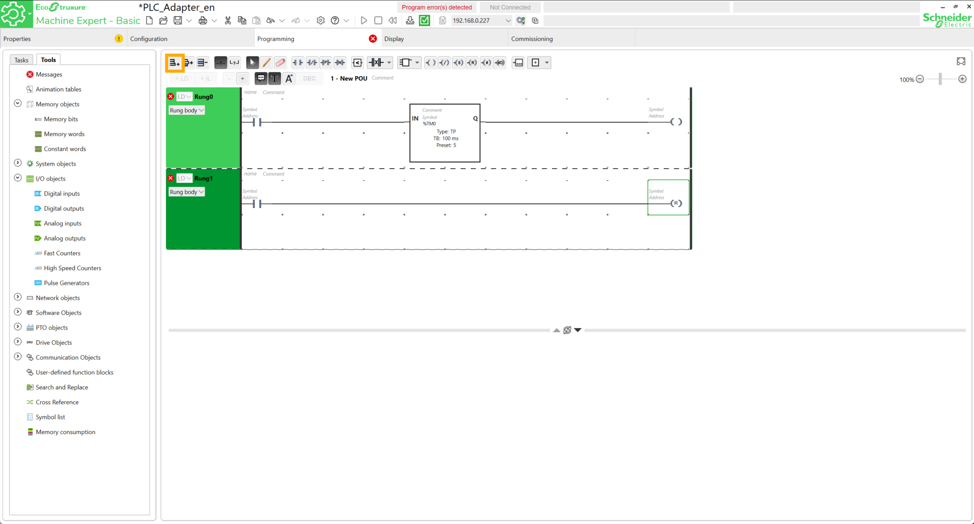
Add a new network, then add a new contact and a reset coil to it.
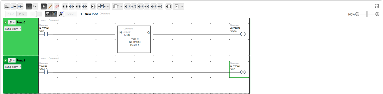
At the first contact, add the address %M0 and for the symbol, put Button1. A window containing a message to confirm the choice should appear. Click Yes.
Fill in the other elements in the same way as shown in the following image.
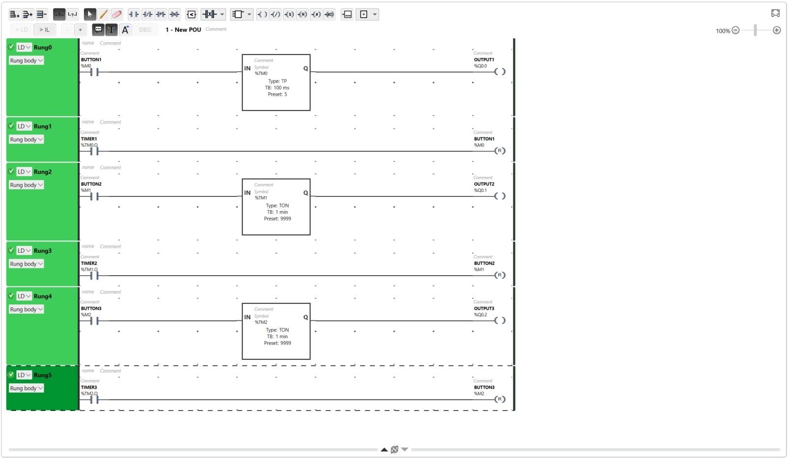
There you go, the first simulated button is created. We can duplicate the same logic to create other buttons.
Robot-side programming
This script allows the robot to be controlled directly by electrical signals sent by the PLC to its ports DI1, DI2, and DI3. In an IDE (Visual Studio), copy the code found here.
Here are some explanations to better understand its role.
1. Hardware Interaction
This code queries the physical state of the robot pins :
-
Reading signals: the robot.digital_read() function continuously monitors if a voltage is present on the inputs.
-
PinState.HIGH: the robot detects if a button is pressed or if the controller sends an "All or nothing" signal (24 V transformed to 5V).
2. Role of Physical Commands
The logic is simplified into three direct actions triggered by each input:
-
DI1 (Input 1): starts the auto calibration procedure to reset the motors.
-
DI2 (Input 2): orders an immediate move to the HOME position.
-
DI3 (Input 3): triggers the Vision Pick & Place cycle.
3. Logic and Stability
-
Control loop: the program scans the inputs every 0.5 seconds (robot.wait(0.5)) to avoid saturating the processor while remaining responsive.
-
Priority: the if/elif structure ensures that only one action is processed at a time, thus preventing the robot from attempting to perform two contradictory movements simultaneously.
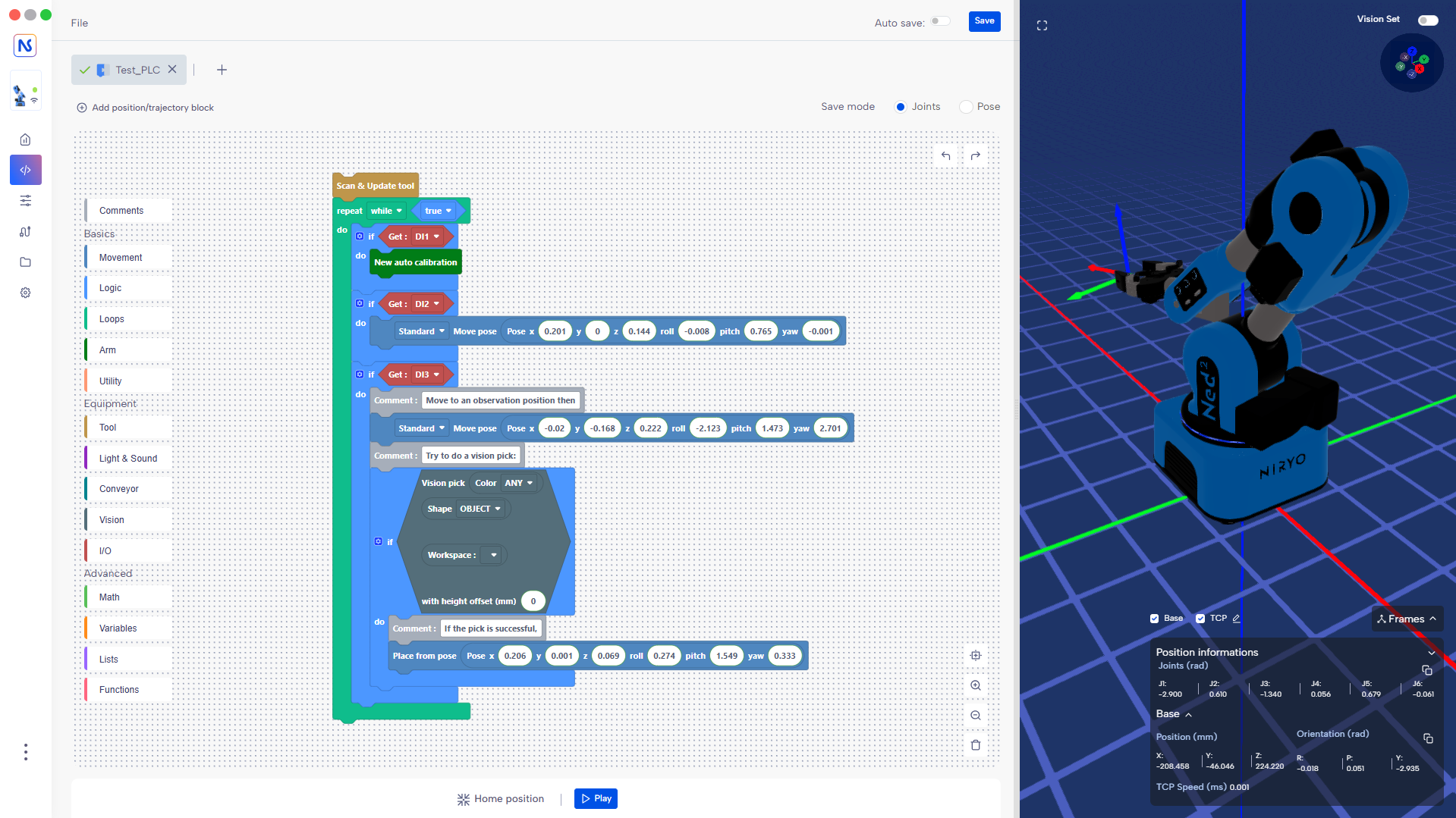
There is a Blockly version, which can be found here.
Tests
On Machine Expert Basic, activate the connection with the PLC, then start the controller. By forcing the value of the BUTTONX contacts, the PLC outputs are activated, allowing the various predefined actions in the robot program to be launched.